Chapter Tests
and Problems
ChaPTer 6 Lines and LeTTering
TesT
INSTRUCTIONS
Answer the questions with short, complete statements or draw–
ings as needed.
QUESTIONS
Part 1: Lines
1. Identify the ASME document that governs line standards.
2. What are construction lines used for, and how should they
be drawn?
3. Discuss line uniformity and line contrast.
4. Should there be any difference in line darkness?
5. What is the recommended thickness of object lines?
6. What do hidden lines represent on a drawing?
7. Describe two functions that centerlines serve on a drawing.
8. Extension lines are thin lines that are used for what purpose?
9. Where should the extension lines begin in relationship to
the object and end in relation to the last dimension line?
10. Describe leaders.
11. What is the correct length-to-width ratio of a properly
drawn arrowhead?
12. Should arrowheads on a drawing all be the same size? Why?
13. Describe the difference between a cutting-plane and a
viewing-plane line.
14. Should cutting-plane lines be drawn thick or thin?
15. Discuss the recommended spacing and angle of section
lines.
16. List two uses for phantom lines.
17. What type of line is used to indicate that a portion of a sur-
face or feature will receive a specific treatment?
18. Describe the line thicknesses recommended by the ASME
standard.
19. How can you draw parallel lines that are very close together,
so the space between the lines does not fill in when the
drawing is reproduced?
20. Give another name for visible lines, describe their purpose
on a drawing, and give their recommended thickness.
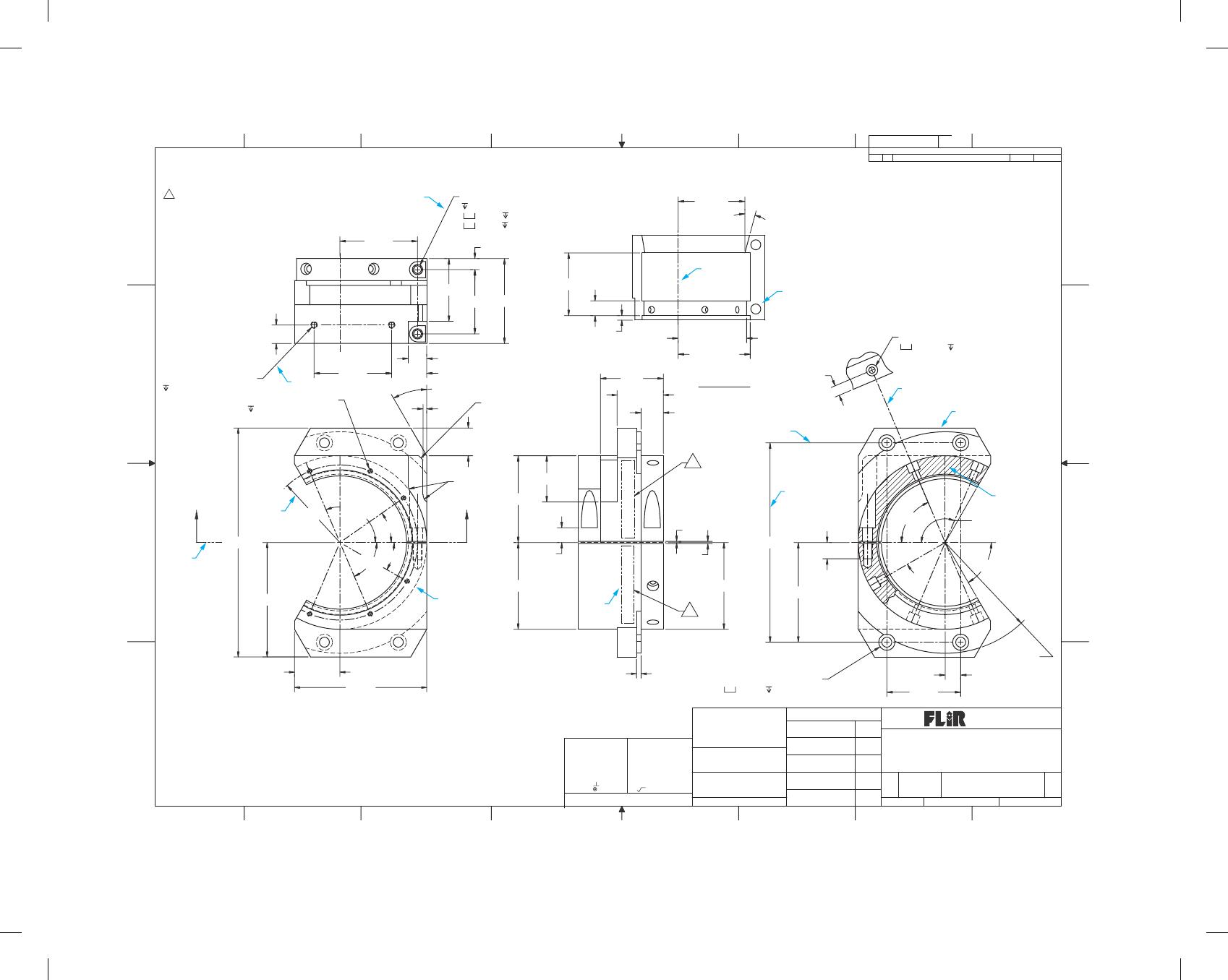
Part 2: Line Identification
Given the print on page 217, identify the lines labeled A through M.
Part 3: Lettering
1. What type of lettering characters are recommended by
ASME for engineering drafting?
2. According to ASME standards, what are the minimum rec-
ommended lettering heights?
3. Define font.
4. Identify two terms that are used for lettering in CADD
terminology.
5. Identify the ASME recommended inch and metric units.
6. Provide the general note placed on drawings to identify the
predominant units used on the drawing.
7. Identify the ASME document that provides the recom–
mended lettering standards.
8. Describe how decimal points should be treated when placed
in numerals.
9. Identify the drafting disciplines that commonly use frac-
tions on drawings, and describe the options used for dis-
playing fractions on drawings.
10. Give the recommended slant for inclined lettering, and
identify at least one drafting discipline where inclined let-
tering is used.
11. Briefly describe lettering legibility requirements on a
drawing.
12. Explain what the ASME standard recommends for the spac-
ing of letters in words, between words, and between lines of
lettering.
13. Define the term default and give an example related to
lettering.
59728_ch06_EOC_ptg01.indd 1 03/02/16 10:23 am
2X
.300
1.7402.300
4X .75
2X .250-20 UNC-2B
SHOWN
4X 30
6.20
R2.100
35
2X 113
1.700
.120
.400
2X R1.950
R1.852
±
.001
VIEW A-A
3.10
2X 1.23
(3.58)
R1.805
15
30
2X 67
1.70
.500
6X .138-32 UNC-2B
.25 MIN
A
2X .250-20 UNC-2B
.30 MIN
.10
R.25
2.100 .95
.50
2.100
30
2X 67
2X .40
2.350
.030
.060
5.400.44 MIN
2X 113
2.700
R2.350
2X .125
2.350
4X ÿ.270
±
.010 THRU
ÿ.44 .43
5
.420
2.000
2X 60
4X R3.000
.60
1.70
1.25
A
.12 X 45
5
5X .280
SHOWN
SHOWN
ÿ.28
ÿ.44
5X ÿ.180 THRU
ÿ.312.25
PROJECT:
DRAWN
CHECK
DESIGN
ENGR
APPR
DATE
TITLE
SIZECAGE DWG. NO.
SCALE PRINTED:
REVISIONS
DESCRIPTIONZONE LTR DATE APPROVED
REVDWG NO.
Portland Or 97224
16505 SW 72nd Ave
FLIR Systems Inc.
CALC. WT.
FINISH
MATERIAL
DIMENSIONS ARE IN INCHES
UNLESS OTHERWISE SPECIFIED
DECIMALS .XX
.XXX
HOLE ˇ .XX
.XXX
ANGLES 0 30′
BENDS
±
2
PERPEND. .003/IN
CONCEN .003/IN
FRACTIONS
±
1/32 STRAIGHTNESS &/OR
FLATNESS: .005/IN
THREADS:
EXTERNAL-CLASS 2A
INTERNAL-CLASS 2B
ANGLES,BENDS, &
INTERSECTIONS: 90
MACHINED SURFACES:
SAMPLES MUST BE APPROVED BY ENG.
PRIOR TO STARTING PRODUCTION
DO NOT SCALE DRAWING
63 OR BETTER
DWG2 REV2
ALL DIMENSIONS IN [ ] ARE MM
±
.005
.003
.001
±
.015
±
.005
7
A
568 4123
B
C
D
A
B
C
D
5678 413
REV
11
SHEET OF
1:1
DATE
DRAWN
PROJECT
D64869
NOTES:
+
–LENS MTG
SADDLE – TELESCOPE
.05 THICK
AL 5052-H32
MIL-C-5541, CL3
CHEM FILM PER
CONTRASTING COLOR, .12 in. HIGH GOTHIC STYLE CHARACTERS, INCLUDE
IDENTIFY IAW MIL-STD-130, BY RUBBER STAMP OR HAND MARK,
PART TO BE FREE OF BURRS AND SHARP EDGES.
DIMENSIONS AND TOLERANCES PER ASME Y14.5-2009.
LATEST REV LEVEL: 64869-XXXXXXXX REV_. LOCATE
APPROX AS SHOWN.
INTERPRET DRAWING IAW MIL-STD-100.
3.
4
2.
1.
G
L
I
J
H
F
C
E
D
B
A
K
M
59728_ch06_EOC_ptg01.indd 2 03/02/16 10:23 am

14. Define justification.
15. What does the term single stroke mean with regard to free–
hand lettering?
59728_ch06_EOC_ptg01.indd 3 03/02/16 10:23 am
26
Chapter 6
Lines and Lettering
Answers to End-of-Chapter Test Questions
Part 1: Lines
27
Part 3: Lettering
29