Chapter 13 GeometriC
DimensioninG anD toleranCinG
test
INSTRUCTIONS
Answer the questions with short, complete statements or draw–
ings as needed.
qUeSTIONS
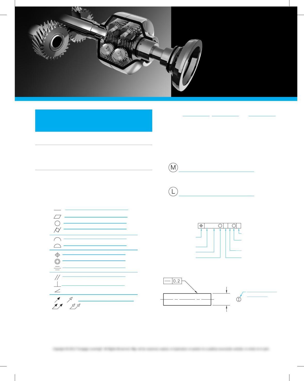
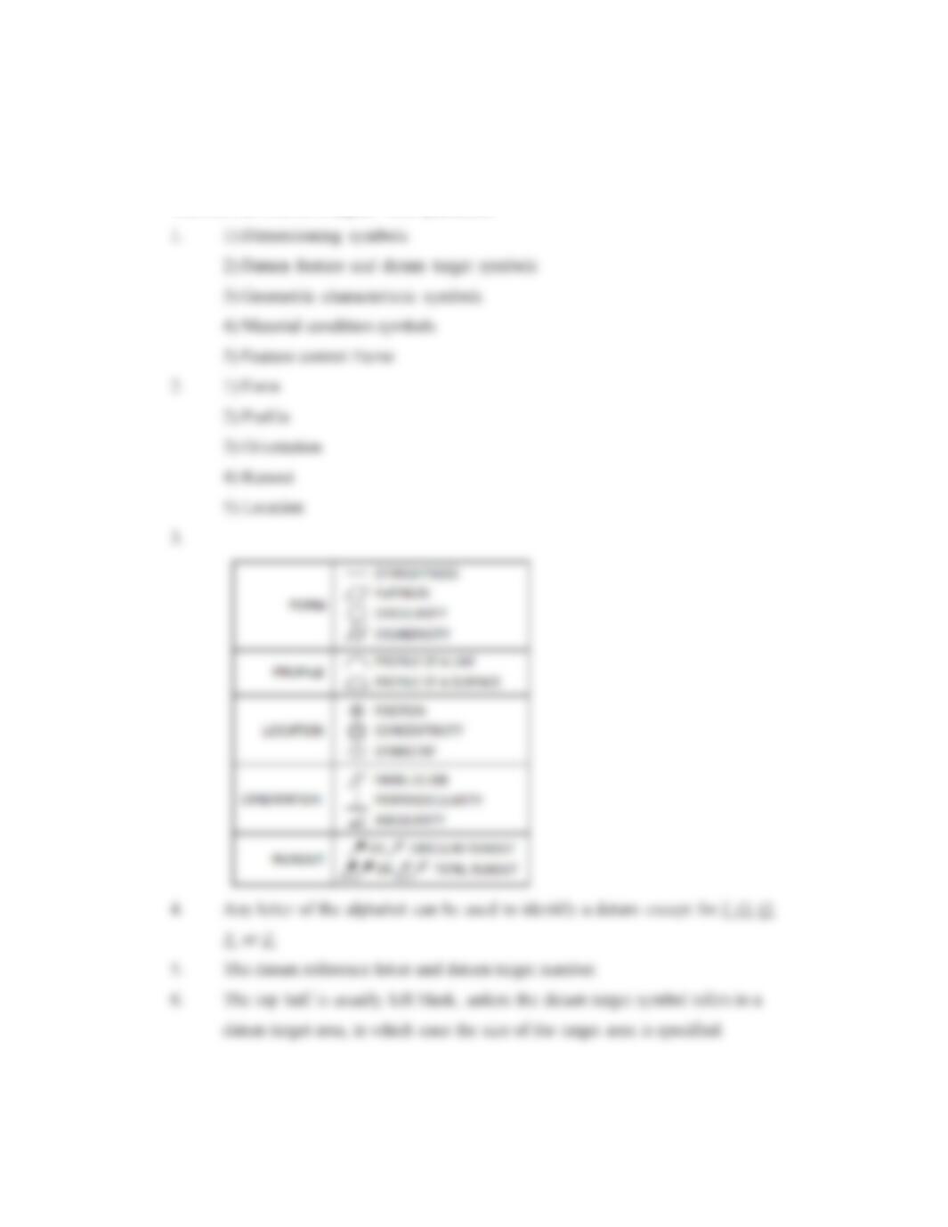
1. List the five basic types of dimensioning and geometric
tolerancing symbols.
2. Name the five types of geometric characteristic symbols.
3. Name each of the following geometric characteristic
symbols.
4. Any letter of the alphabet can be used to identify a datum ex–
cept for , , and .
5. What information is placed in the lower half of the datum
target symbol?
6. What information is placed in the top half of the datum
target symbol?
7. Given the following symbols, provide the meaning of each
symbol in the spaces to the right.
8. Name each of the elements in the following feature control
frame.
MM
Ø 0.13 AB C
E
F
G
H
A
B
C
D
9. Label the symbol in the following application using the
blank provided.
Ø6 ± 0.5
10. Completely define the term basic dimension.
Chapter tests
and problems
59728_ch13_EOC_ptg01.indd 1 2/3/16 2:21 PM
11. How are basic dimensions shown on a drawing?
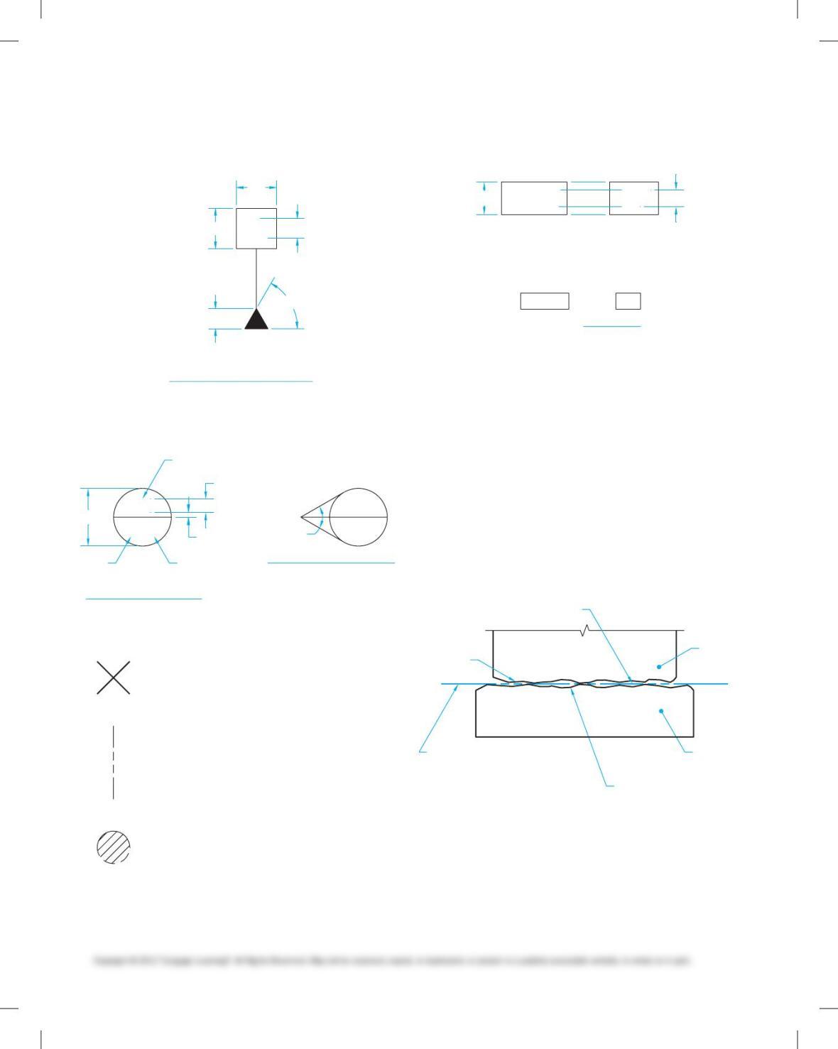
12. Name the following symbol and identify the proper drafting
dimensions B through F and put symbol name at A.
A
A
C
BD
E
F
13. Name the following symbols and identify the proper draft-
ing dimensions and features C through G and put symbol
name at A and B.
Ø8
A1 A1
E
G
D
H
F
C
I
A
B
14. Name the following symbols.
B
C
A
15. Name the following symbol and identify the proper drafting
dimensions A and B.
AB
63.5
6 X 45° 6 X 45°
45°
Symbol name
16. Define datum.
17. Define datum feature.
18. Describe datum feature simulators. Include the term simu–
lated datums in your description and give at least three ex–
amples of datum feature simulators used in manufacturing.
19. Identify at least five locations where a feature control frame
can be placed on a drawing.
20. Define datum plane.
21. List at least five items that can be considered as datum fea-
tures on an object or part.
22. Identify the datum feature, the part, the simulated datum
plane, the physical datum feature simulator, and the datum
plane labeled A through F on the following illustration.
D
E
F
B
C
A
23. Identify at least three required conditions for datum feature
simulators.
24. Define actual mating envelope.
25. Define tangent plane.
59728_ch13_EOC_ptg01.indd 2 2/3/16 2:21 PM
26. Name the three datums of a complete datum reference
frame.
27. When referring to the datum reference frame in the feature
control frame, the datum is given first fol-
lowed by the and datums.
This is known as the datum .
28. Define degrees of freedom.
29. Define datum targets.
30. The primary datum plane must be established by at least
point(s) on the primary datum surface.
31. The secondary datum plane must be established by at least
point(s) on the secondary datum surface.
32. The tertiary datum plane must be established by at least
point(s) on the tertiary datum surface.
33. How is a datum target area represented on a drawing?
34. How are datum target areas treated on a drawing when the
target area is too small to draw?
35. Describe how to properly display the symbols for a circular
datum target area, a square datum target area, a rectangular
datum target area, and a spherical datum target area.
36. What does a movable datum target symbol indicate?
37. How are datum target lines represented on a drawing?
38. When a portion of a surface is used to establish a single da-
tum, this is referred to as a(n) datum
surface.
39. Two or more surfaces that are on the same plane are re-
ferred to as surfaces.
40. Depending on the functional requirements of a part, more
than one datum reference frame can be established. This is
referred to as a(n) datum reference frame.
41. Describe the basic function of the continuous feature
symbol.
42. Define perfect form boundary.
43. Define regardless of feature size (RFS).
44. How is a feature control frame connected to a related fea-
ture when surface control is intended?
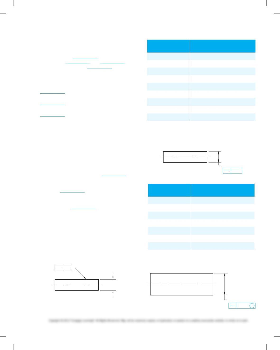
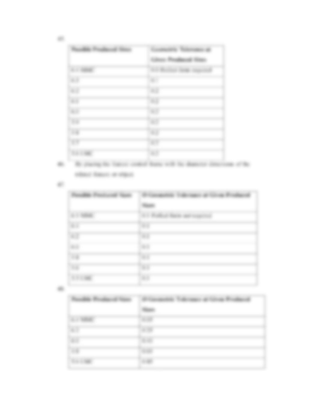
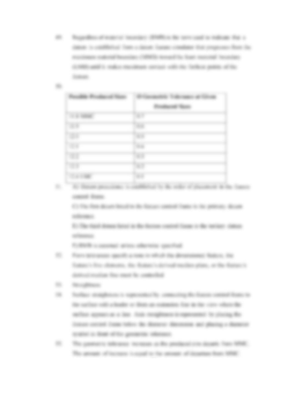
45. Given the following drawing and a list of possible produced
sizes, specify the geometric tolerance at each possible
produced size.
Ø6 ± 0.4
0.2
possible produced
sizes
Geometric tolerance at Given
producedsizes
6.4 MMC
6.3
6.2
6.1
6.0
5.9
5.8
5.7
5.6 LMC
46. How is an axis geometric control specified?
47. Given the following drawing and a list of possible produced
sizes, specify the geometric tolerance at each possible pro-
duced size.
Ø6 ± 0.5
Ø 0.1
possible produced
sizes
\ Geometric tolerance at
Given produced sizes
6.5 MMC
6.4
6.2
6.0
5.8
5.6
5.5 LMC
48. Given the following drawing and a list of possible produced
sizes, specify the geometric tolerance at each possible
produced size.
Ø6 ± 0.4
Ø 0.05 M
59728_ch13_EOC_ptg01.indd 3 2/3/16 2:21 PM
possible produced
sizes
\ Geometric tolerance at Given
produced sizes
6.4 MMC
6.2
6.0
5.8
5.6 LMC
49. Give the proper abbreviation and definition for regardless of
material boundary.
50. Given the following drawing and a list of possible produced
sizes, specify the geometric tolerance at each possible pro-
duced size.
THE DRAWING
12.4
11.8
Ø
Ø 0.
1A
L
possible produced
sizes
\ Geometric tolerance at Given
produced sizes
11.8 MMC
11. 9
12.0
12.1
12.2
12.3
12.4 LMC
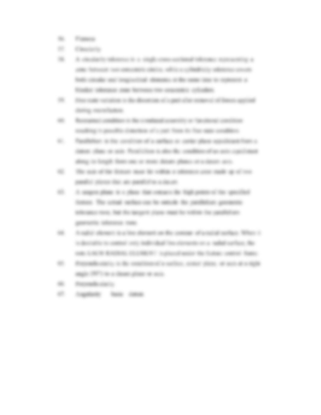
51. Which of the following statements are true in regard to da-
tum precedence and datum reference? (More than one can
be true.)
A) Datum precedence is established by the order of place-
ment in the feature control frame.
B) Datum precedence is established by alphabetical order
of datum reference letters.
C) e first datum listed in the feature control frame is the
primary datum reference.
D) “A” is always the primary datum.
E) e third datum listed in the feature control frame is the
tertiary datum reference.
F) RMB is assumed unless otherwise specified.
52. Define form tolerances.
53. Name the geometric tolerance that specifies a zone within
which the required surface element or axis must lie.
54. Explain the difference between the methods used to repre-
sent surface and axis straightness.
55. Axis straightness can be specified on an MMC basis by plac-
ing the MMC symbol after the geometric tolerance in the
feature control frame. The specified geometric tolerance is
held at the MMC produced size. Explain what happens to
the geometric tolerance as the produced size departs from
MMC.
56. What geometric tolerance establishes the distance between
two parallel planes within which the surface must lie?
57. Which geometric tolerance is characterized by any given
cross section taken perpendicular to the axis of a cylinder or
cone or through the common center of a sphere?
58. What is the difference between the circularity geometric
tolerance and the cylindricity geometric tolerance?
59. Define free state variation.
60. Define restrained condition.
61. Define parallelism.
62. What does it mean when a feature control frame with a par-
allelism geometric characteristic symbol is placed below a
diameter dimension?
63. Define tangent plane and describe the relationship among
the actual surface, the tangent plane, and the geometric
tolerance.
64. Define radial element and describe how a radial element
specification is applied to a drawing.
65. Define perpendicularity.
66. A tolerance is established by a geometric
tolerance zone made up of two parallel planes that are a
basic 908 to a given datum plane or axis where the actual
surface must lie.
67. A(n) geometric tolerance zone is established
by two parallel planes at any specified basic angle, other
than 908, to a datum plane or axis. The specified angle must
be , and it must be dimensioned from the
plane.
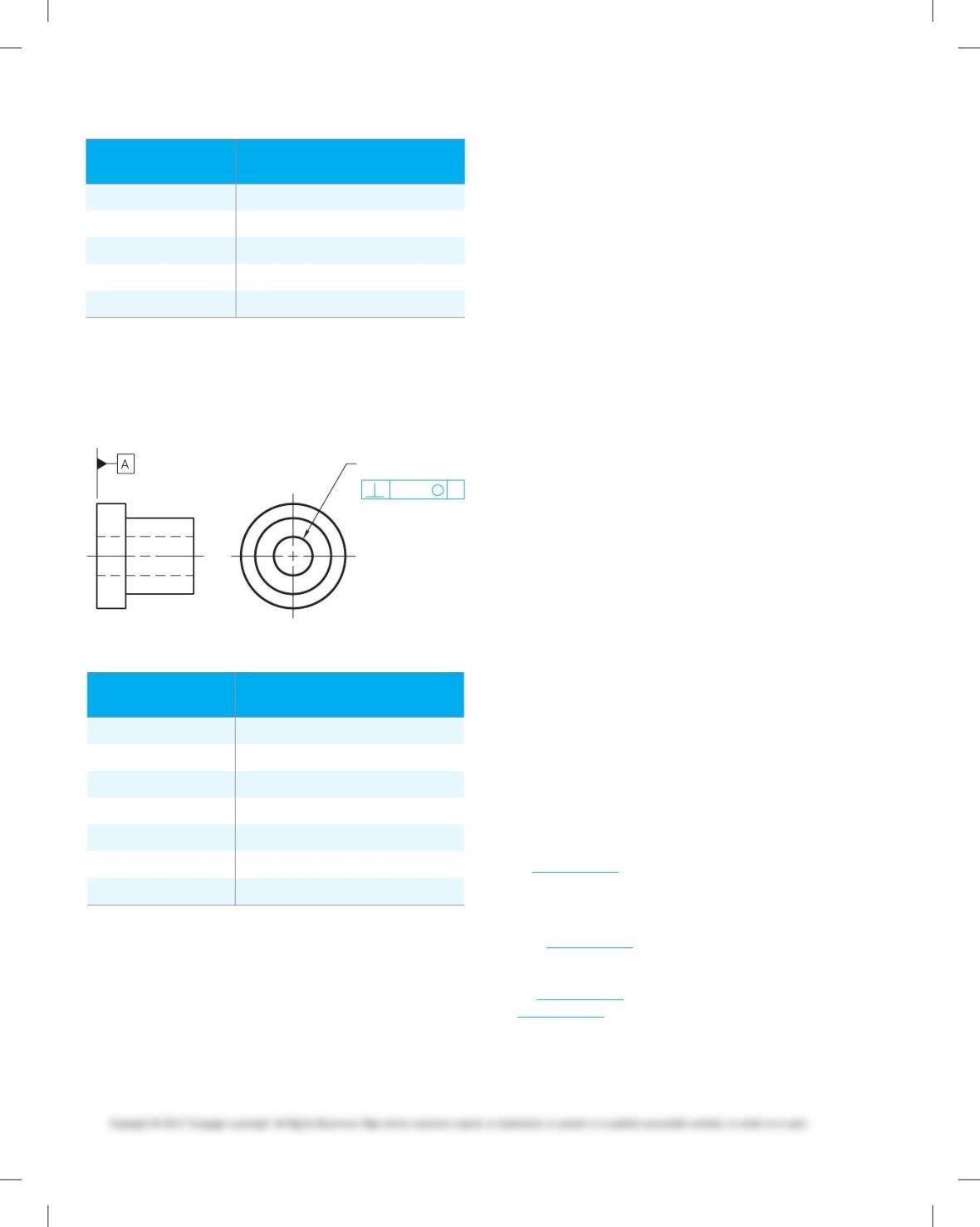
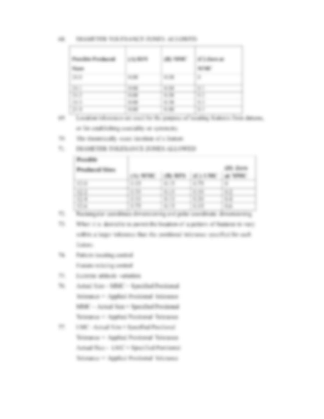
68. Given the following drawing, a reference chart showing a
range of possible produced sizes, and three optional feature
control frames that can be applied to the diameter
59728_ch13_EOC_ptg01.indd 4 2/3/16 2:21 PM
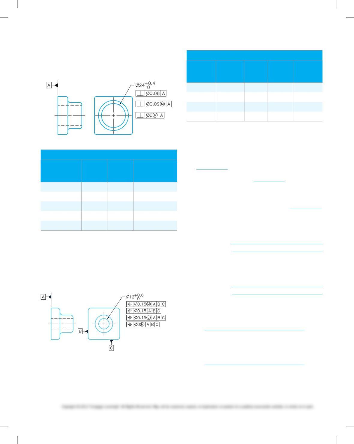
dimension, provide the geometric tolerance at each
possible produced size for each feature control frame
application.
A
B
C
Diameter tolerance Zones allowed
possible
produced
sizes (a) rFs (B) mmC
(C) Zero
at mmC
24.0
24.1
24.2
24.3
24.4
69. Describe the purpose of location tolerances.
70. Define true position.
71. Given the following drawing, a reference chart showing a
range of possible produced sizes, and four optional feature
control frames that can be applied to the diameter dimen-
sion, provide the positional tolerance at each possible pro-
duced size for each feature control frame application.
Optional feature control frames
A
B
C
D
Diameter tolerance Zones allowed
possible
produced
sizes (a) mmC (B) rFs (C) lmC
(D) Zero
atmmC
12.0
12.2
12.4
12.6
72. Name the two types of dimensioning systems that are nor-
mally used when locating multiple features.
73. Describe when composite positional tolerancing is used.
74. When using composite positional tolerancing, the upper
part of the feature control frame is referred to as the
and specifies the larger tolerance for the pat-
tern of features as a group, while the lower half of
the frame is called the and specifies a
smaller positional tolerance for individual features within
the pattern.
75. When the axis of a hole is at an extreme angle inside the
positional tolerance zone, it is referred to as .
76. Give the formulas for internal and external features that can
be used when calculating the positional tolerance at any
produced size when MMC is applied to the positional
tolerance.
Internal feature:
External feature:
77. Give the formulas for internal and external features that can
be used when calculating the positional tolerance at any
produced size when LMC is applied to the positional
tolerance.
Internal feature:
External feature:
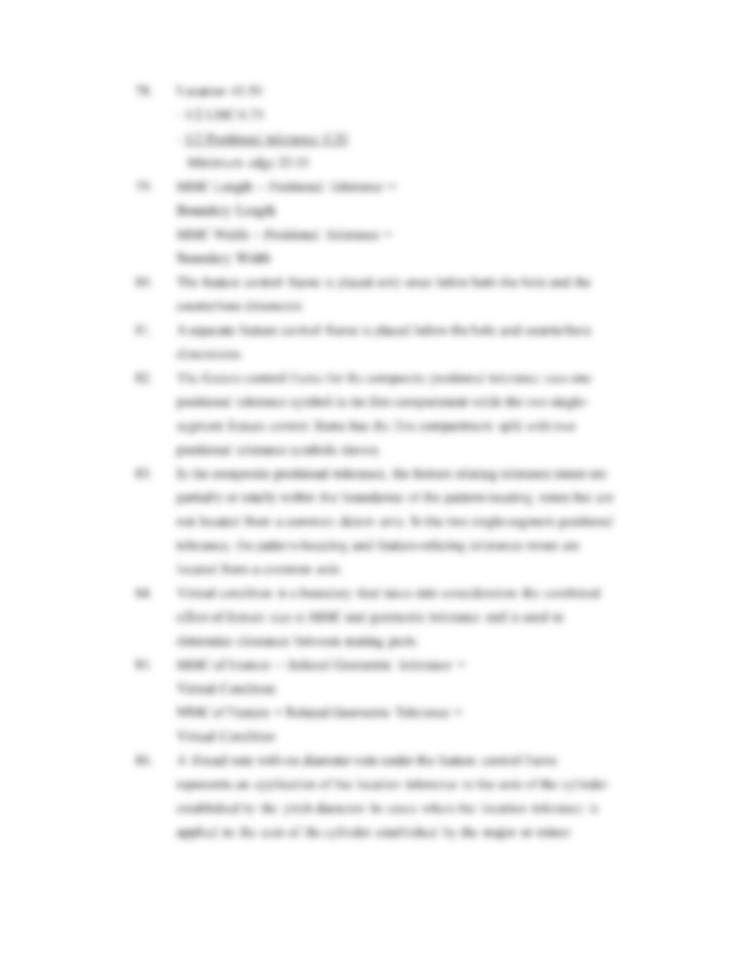
78. Calculate the minimum edge distance or minimum wall
thickness between the edge of a hole and the outside surface
of the part for an LMC positional tolerance application given
the following information (dimensions are in millimeters).
Location dimension:
Positional tolerance:
MMC of hole:
LMC of hole:
Calculations:
40.5
0.4
12.5
13.5
79. Give the formulas for calculating the slot boundary when
applying positional tolerancing to slotted features.
59728_ch13_EOC_ptg01.indd 5 2/3/16 2:21 PM
80. How is the feature control frame placed in relation to a hole
and counterbore when the positional tolerance is the same
for the hole and counterbore?
81. How is the feature control frame placed in relation to a hole
and counterbore when the positional tolerance is different
for the hole and counterbore?
82. What is the difference between the appearance of the feature
control frame used for a composite positional tolerance and
the one used for a positional tolerance with two single
segments?
83. Explain the primary difference between the composite
positional tolerance and the two single-segment positional
tolerance as applied to circular patterns.
84. Defne virtual condition.
85. Give the formulas for calculating virtual condition for inter–
nal and external features.
Internal feature:
External feature:
86. Describe how a thread note looks when a location tolerance
applied to the axis of the cylinder is established by the pitch
diameter, and how this compares to applications when a
location tolerance applied to the axis of the cylinder is es-
tablished by the major or minor diameter.
87. Give the formula used to determine the positional tolerance
of a floating fastener.
88. Give the formula used to determine the positional tolerance
of a fixed fastener.
89. Under which condition(s) is a projected tolerance zone
recommended?
90. Identify the two ways that a projected tolerance zone can be
shown on a drawing.
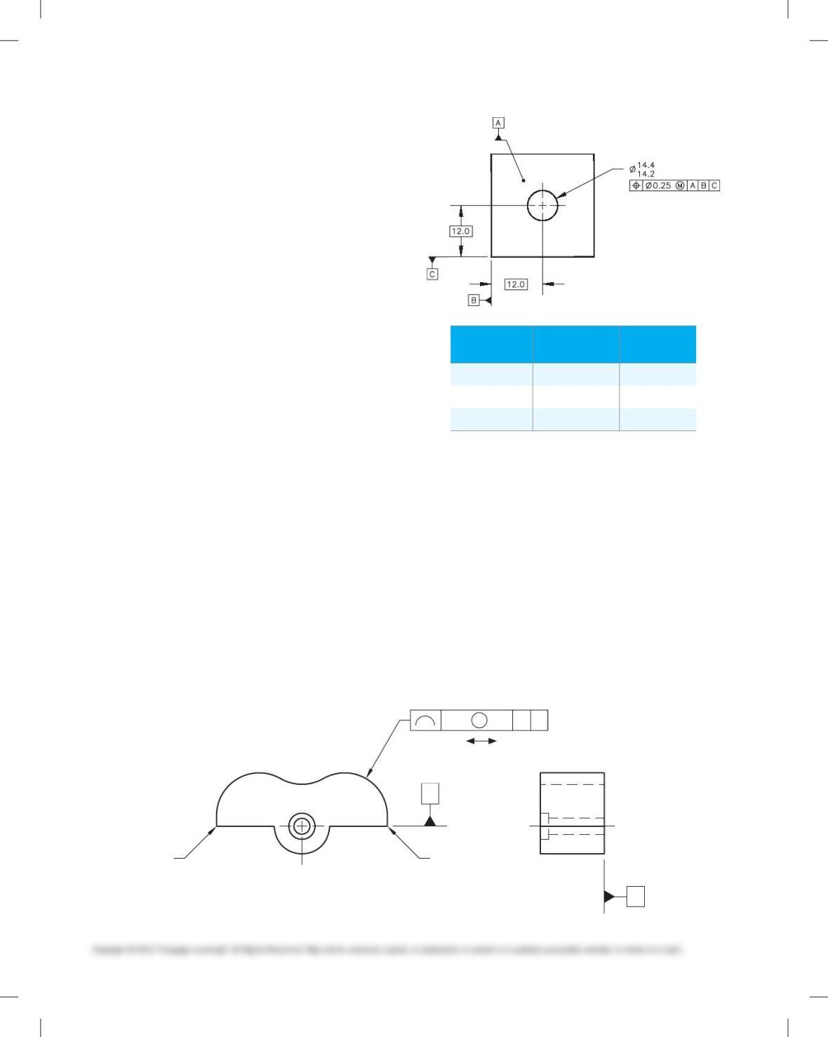
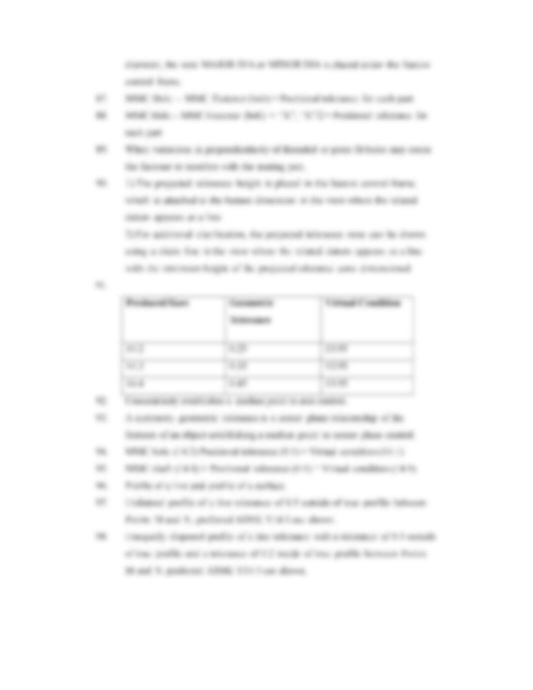
91. Given the following drawing and a range of possible pro-
duced sizes, provide the geometric tolerance and virtual
condition at each possible produced size.
produced
sizes
Geometric
tolerance
Virtual
Condition
14.2
14.3
14.4
92. Define concentricity.
93. Describe the symmetry geometric tolerance.
94. Calculate the virtual condition of a hole through a part
where the hole diameter is 14.5 0.3 and the associated
positional tolerance is 0.1 at MMC. Show your
calculations.
95. Calculate the virtual condition of a pin that extends 15 mm
above the primary datum of a part where the pin diameter
is 14.5 0.3 and the associated perpendicularity toler-
ance is 0.1 at MMC. Show your calculations.
96. Name the two types of profile geometric tolerances.
97. Given the following drawing, describe the profile geometric
tolerance and related drawing specifications. Indicate
whether the drawing shows preferred ASME Y14.5 use or an
alternate practice.
2 SURFACES
B
A
MN
MN
0.5 0.5UAB
NOTE: ASSUME THE SHAPE BETWEEN
M AND N IS DEFINED WITH BASIC
DIMENSIONS RELATIVE TO DATUM B.
59728_ch13_EOC_ptg01.indd 6 2/3/16 2:21 PM
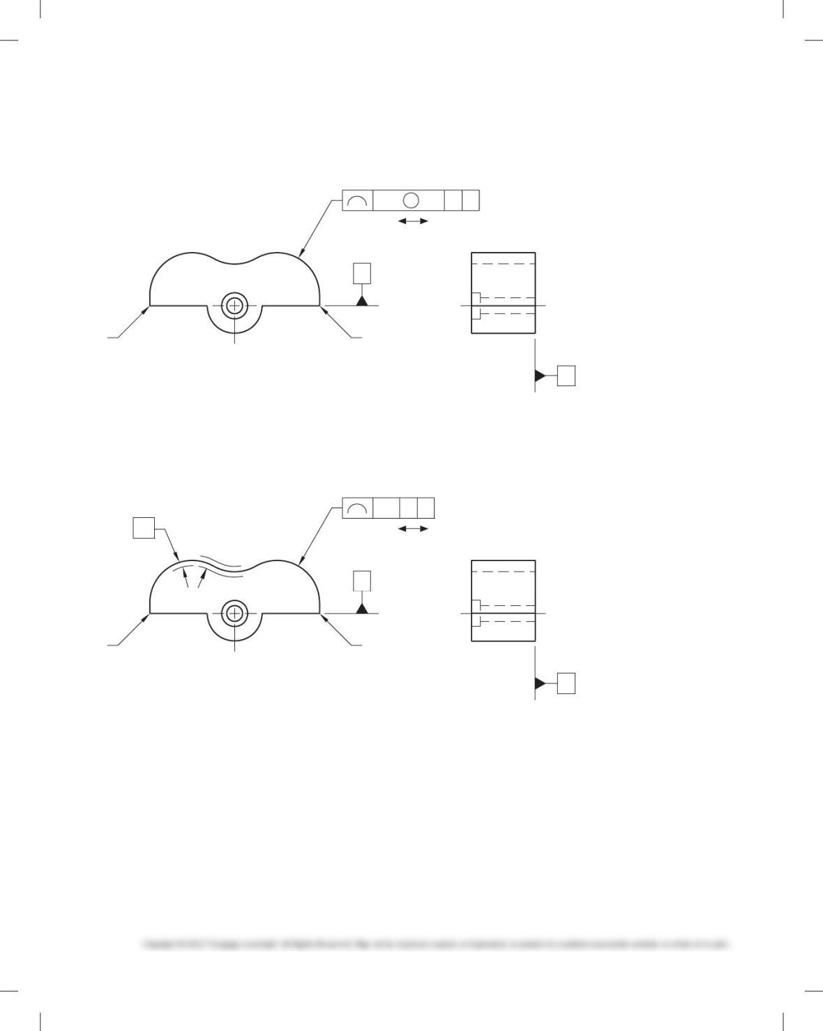
98. Given the following drawing, describe the profile geometric
tolerance and related drawing specifications. Indicate
whether the drawing shows preferred ASME Y14.5 use or an
alternate practice.
2 SURFACES
B
A
MN
MN
0.5 0.3UAB
NOTE: ASSUME THE SHAPE BETWEEN
M AND N IS DEFINED WITH BASIC
DIMENSIONS RELATIVE TO DATUM B.
99. Given the following drawing, describe the profile geometric
tolerance and related drawing specifications. Indicate
whether the drawing shows preferred ASME Y14.5 use or an
alternate practice.
2 SURFACES
B
A
0.2
MN
MN
0.5 AB
NOTE: ASSUME THE SHAPE BETWEEN
M AND N IS DEFINED WITH BASIC
DIMENSIONS RELATIVE TO DATUM B.
100. Define runout.
59728_ch13_EOC_ptg01.indd 7 2/3/16 2:21 PM
55
Chapter 13
Geometric Dimensioning and Tolerancing
Answers to End-of-Chapter Test Questions

58
59
60
61
62
63
64
65
66