Chapter Tests
and Problems
ChaPTer 10 Dimensioning
anD ToleranCing TesT
INSTRUCTIONS
Answer the questions with short, complete statements or draw–
ings as needed.
QUESTIONS
1. Name two classifications of dimensions.
2. Identify and describe two types of notes.
3. Define unidirectional dimensioning.
4. Specify the ASME document that governs the standard for
dimensioning and tolerancing.
5. Define the following terms; examples can be used if appro-
priate: actual size; bilateral tolerance; dimension; feature;
limits of dimension; specified dimension; tolerance; unilat–
eral tolerance.
6. What are the recommended standard units of linear mea–
surements on engineering documents?
7. When all dimensions are metric, what is the general note
that should accompany the drawing?
8. Give the standard height of dimension text.
9. How should the decimal in numerals be treated?
10. Should all of the dimension arrowheads on a drawing be the
same size?
11. What is the recommended length-to-height ratio of
arrowheads?
12. Discuss proper dimension line spacing.
13. Identify a possible disadvantage of chain dimensioning.
14. Describe baseline dimensioning.
15. How are notes for holes dimensioned on an engineering
document?
16. Describe how holes are located.
17. Define maximum material condition (MMC).
18. Define least material condition (LMC).
19. Describe a clearance fit.
20. Describe running and sliding fits (RC), locational fits (LC,
LT, LN), and force fits (FN).
21. List three factors that influence sheet size selection.
22. Identify two factors that influence drawing scale selection.
23. Define casting. (See Chapter 5.)
24. Define core. (See Chapter 5.)
25. Define forging. (See Chapter 5.)
26. Explain the purpose of draft angle on a casting or forging.
27. Define surface finish.
28. Identify the units used to measure surface roughness height.
29. Show three examples of the recommended placement of
surface finish symbols.
30. Describe the surface condition and process used to estab-
lish the following surface roughness heights given in mi-
crometers: 12.5, 6.3, 3.2, 1.6, 0.80, 0.20, 0.050. Appendix E is a
reference in addition to this chapter content.
31. Describe tabular dimensioning.
32. Where are general notes generally placed when using ASME
standards?
33. Where are the general notes placed when using Military
standards?
34. Describe a delta note and when it is used.
35. Define parting line.
36. What does it mean when a note such as .010 MAX DRAFT
ANGLE is applied to the drawing for a plastic part?
37. Explain what 1DFT means when applied to a dimension.
38. What does 2DFT mean when applied to a dimension?
39. Discuss the possible results of designing a part with specifi-
cations that require overmachining.
40. Explain the difference between jigs and fixtures.
59728_ch10_EOC_ptg01.indd 1 03/02/16 10:26 am
41. Normally a jig or fixture is drawn as an assembly of the unit
ready for use, and the workpiece or part to be held is drawn
in position. How is the workpiece drawn in relationship to
the jig or fixture?
42. Describe the use of drill jigs.
43. Drill fixtures are sometimes referred to as what?
44. Describe the use of drill fixtures.
45. Explain how machining fixtures work.
46. Describe the function of welding fixtures.
47. Briefly explain the use of inspection fixtures.
48. Define and describe the use of progressive dies.
49. What is a pickoff jig?
50. Why is it important for a tool designer to be a good print
reader?
51. Identify at least four qualities that tools must have.
52. What does ISO stand for?
53. Briefly explain the purpose of the ISO 9000 Quality Systems
Standard.
54. Give the name of the organization that represents the United
States in the ISO 9000.
55. Give at least five reasons why an organization might want to
have an ISO 9000 registration.
56. Explain the purpose of the ISO 9000-1.
57. Briefly describe the function of the ISO 9001.
58. Describe the ISO 9002 standard.
59. What is the purpose of the ISO 9003 standard?
60. Explain the purpose of the ISO 9004-1 standard.
61. Give the name of the ISO 9001 standard that has been spe-
cifically related to the automotive industry.
62. Name the ISO 9001 standard that has been specifically re-
lated to the aerospace industry.
Part 2: General Tolerancing
63. Identify the tolerance and limits of each of the following
dimensions:
Metric: 25.5 6 0.1; 19 6 0.25.
Inch: .375 6 .003; 1.6250 6 .0005.
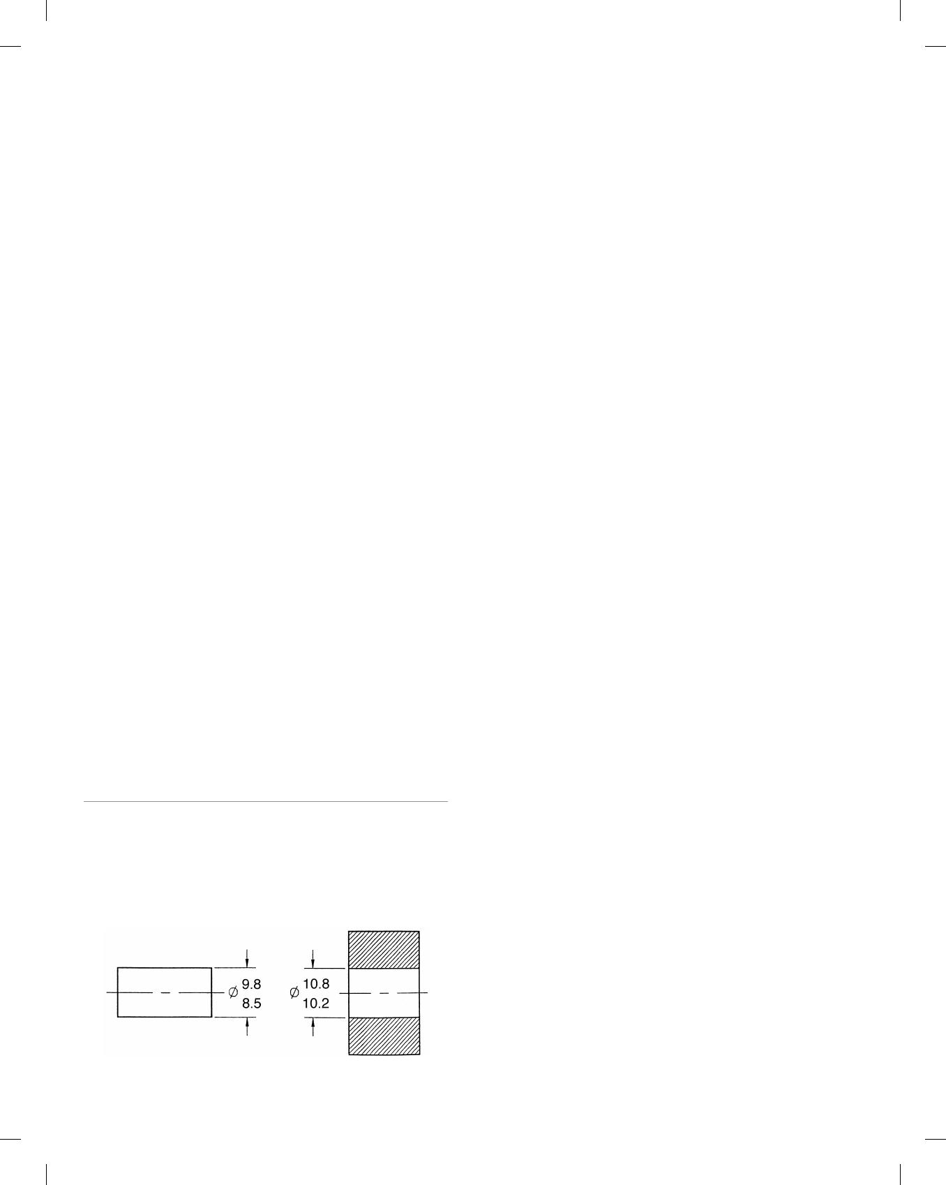
64. Given the following CAD drawing, calculate the allowance.
Show and label the elements of your calculation.
65. From the following list of given conditions, calculate the
limits of the shaft and the limits of the hole. Show and label
the elements of your calculations. (Review the allowance
calculation formula.)
a. Metric dimensions.
b. A clearance fit.
c. Allowance 5 0.05.
d. Specified dimension of shaft 5 12.
e. Shaft tolerance 5 0.26 BILATERAL. (Remember the toler–
ance is the total permissible variation.)
f. Hole tolerance 5 0.18.
66. Determine the shaft and hole limits for a 1 in. diameter shaft
using an RC4 fit. Show and label the elements of your
calculations.
67. Establish the shaft and hole limits for a .25 in. diameter shaft
using an RC4 fit. Show and label the elements of your
calculations.
68. Calculate the shaft and hole limits for a 1.125 in. diameter
shaft using an RC4 fit. Show and label the elements of your
calculations.
69. Using standard metric limits and fits with tolerances of
close running fits, determine the limits of a 30-mm hole.
Display the required dimension with limits followed by the
code in parentheses.
70. By means of standard metric limits and fits with tolerances
of close running fits, determine the limits of a 30-mm shaft.
Show the required dimension with limits followed by the
code in parentheses.
71. With standard metric limits and fits using close running fits,
determine the limits of a 25-mm hole. Give the required di-
mension with limits followed by the code in parentheses.
72. Using standard metric limits and fits with tolerances of
close running fits, determine the limits of a 25-mm shaft.
Display the required dimension with limits followed by the
code in parentheses.
73. Name five items that a CADD system needs in order to place
a dimension.
74. Define layering.
75. List at least two reasons why CADD layering can assist the
dimensioning process.
ChaPT
D
59728_ch10_EOC_ptg01.indd 2 03/02/16 10:26 am
38
Chapter 10
Dimensioning and Tolerancing
Answers to End-of-Chapter Test Questions
Part 1: General
39
40
41
42
43
44
45