42
TEST QUESTIONS & PROBLEMS – CHAPTER #5
Short Answer Questions
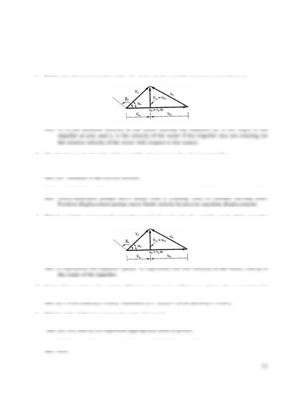
1. Define the physical meaning of Vo, βo, and υo in the centrifugal pump vector diagram.
2. The fundamental principle of the centrifugal pump was first demonstrated by:
a) Manning b) Chezy c) Darcy-Weisbach
d) Hazen-Williams e) Demour f) Wojak-Vieck
3. What is the difference between a turbo hydraulic pump and a positive displacement pump?
4. Which variables represent the impeller speed, the exit velocity, and the angle of the impeller
in the vector diagram below?
5. Using the equations for motor efficiency and pump efficiency, derive the expression for
overall efficiency of a pump system (sometimes called the wire to water efficiency).
6. Which of the following represents units of power?
a) work/time b) hp (horsepower) c) kW (kilowatts) d) dynes
7. (T or F) Pumps add energy to a fluid primarily in the form of increased pressure.

43
8. (T or F) Pumps add energy to a pipeline; thus the outflow from a pump exceeds the inflow.
9. Propeller blades may be mounted on the same axis of rotation in a common housing to form
a multistage propeller pump. What is the advantage of this configuration?
10. (T or F) Propeller pumps move a lot of water, but they do not overcome a lot of head.
11. Describe two differences between an propeller (axial-flow) pump and a centrifugal pump. Is
the theory of both based on the principle of impulse-momentum?
12. (T or F) Jet pumps are often used in combination with centrifugal pumps and have a high
efficiency.
13. Centrifugal pump curves (Hp vs. Q) start at a high head, low flow rate and trend downward
with increasing flow. What is the reason for this?
14. On centrifugal pump curves (Hp vs. Q), the point where Q = 0 and Hp = Hp(max) is called the
a) shut-off head b) rated capacity c) brake horsepower d) match point e) no idea!!
15. Draw a typical pump characteristic curve and label the axes. Then draw a typical system
curve on the same graph. Label the match point and the shut-off head. Now draw a
typical efficiency curve on the same graph.
16. Centrifugal pump characteristic curves are a plot of Q vs. which of the following
a) pump head b) rated capacity c) brake horsepower d) efficiency e) friction loss
17. What is the difference between the match point and the shut-off head?
44
18. Which of the following statements about pumps are false?
a) Pumps operate under maximum efficiency over a very broad range of discharges.
b) The shut-off head is the height water can be raised but produce no flow.
c) Pump discharge increases with decreasing pump head.
d) Two identical pumps in parallel on one discharge line will double the flow rate.
e) Pump selection involves superimposing a system curve on a pump characteristic curve.
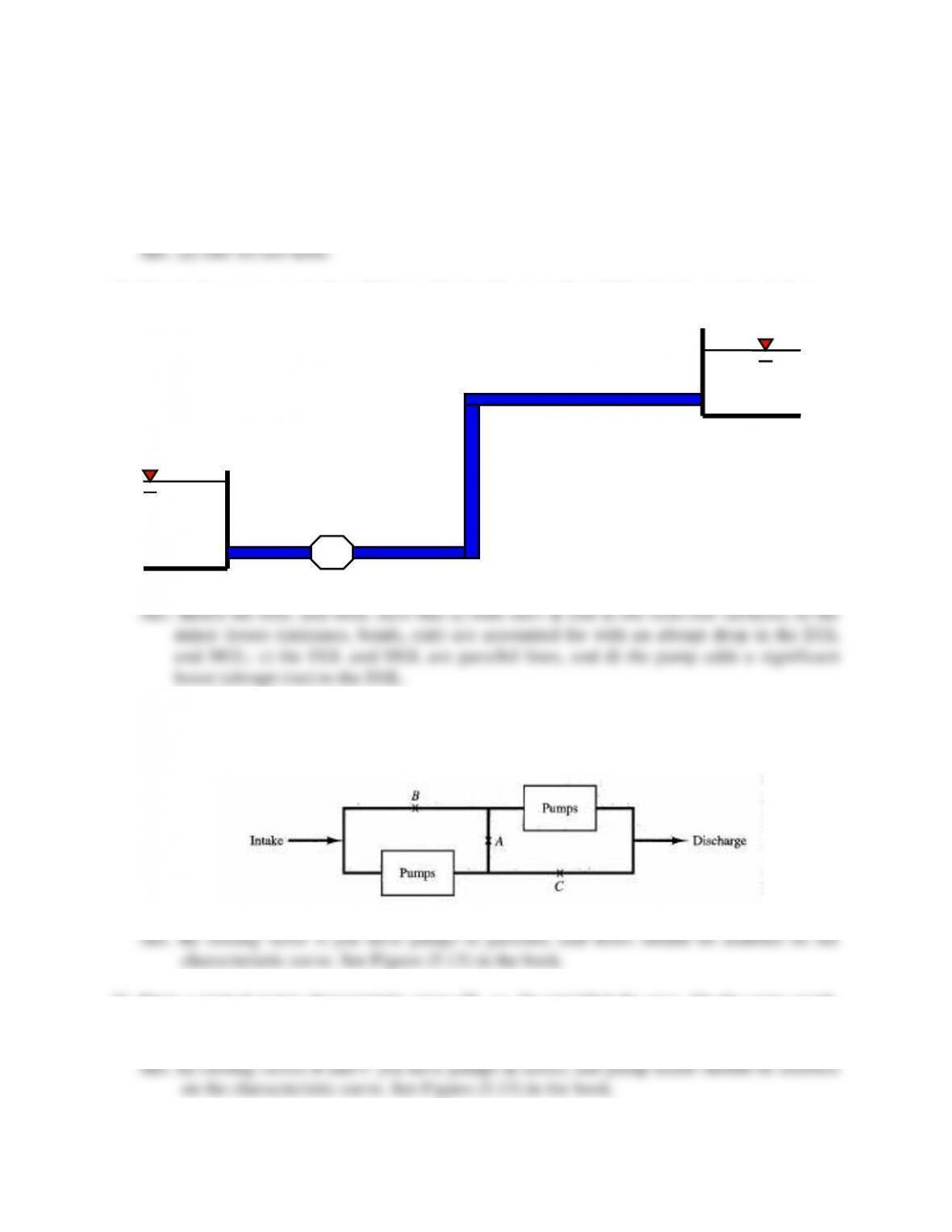
19. Sketch the energy grade line (EGL) and hydraulic grade line (HGL) for the pipeline below.
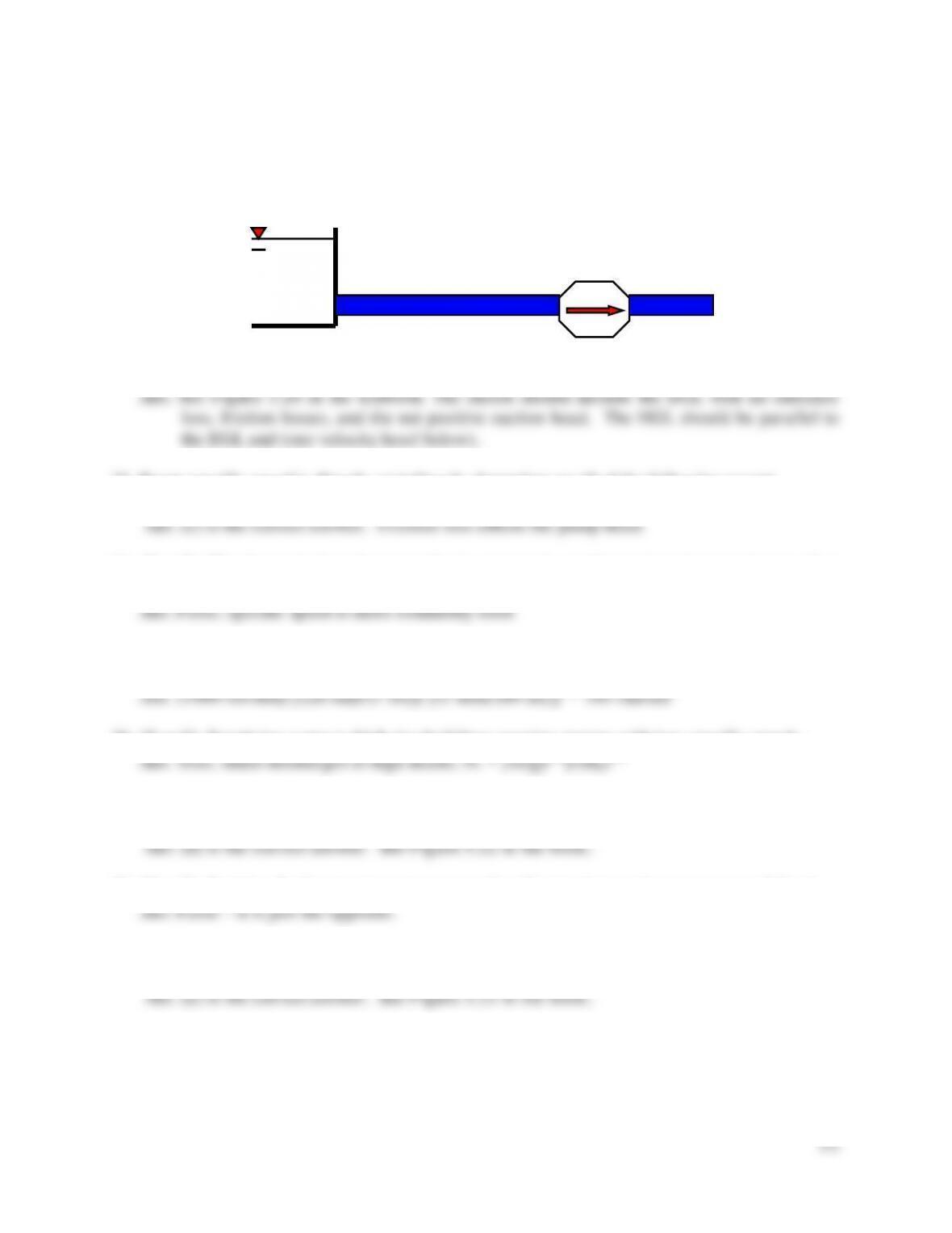
20. Draw a typical pump characteristic curve (Hp vs. Q) and label the axes. On the same graph,
sketch the characteristic curve for the system of identical pumps depicted below if valve A is
closed and valves B and C are open.
21. Draw a typical pump characteristic curve (Hp vs. Q) and label the axes. On the same graph,
sketch the characteristic curve for the system of identical pumps depicted in Question 20 if
valve A is open and valves B and C are closed.
Pump

45
22. Draw a typical pump characteristic curve (Hp vs. Q) and label the axes. On the same graph,
sketch the characteristic curve for the system of identical pumps depicted in Question 20 if
valve A is open and valves B and C are replaced by two more identical pumps making a four
pump arrangement.
23. (T or F) By placing two identical pumps in a pipeline in a parallel configuration, you can
expect to double the discharge.
24. (T or F) A pump is placed in a branching pipeline and is required to pump water from a
supply reservoir to two receiving reservoirs. The total discharge will be split between the two
pipes such that an equal amount of head is added to each of the two pipelines.
25. How is a pipe network analysis modified to incorporate a pump?
26. Many factors contribute to the loss of pressure on the suction side of pumps. Of those listed
here, which does the designer of pumps have the most control over to avoid cavitation.
a) position of the pump b) screen loss c) friction loss d) entrance loss e) “b” and “d”
27. Give three examples of head losses that can be encountered on the suction side of pumps that
may contribute to the loss of pressure and cavitation problems.
28. (T or F) To avoid cavitation in a pump, one of the few parameters that the designer has much
control over is the position of the pump.
29. To avoid cavitation in a pump, one of the few items that a designer has control over is the
a) vapor pressure b) velocity head c) position of the pump d) suction line head losses
30. Where is cavitation most likely to occur in a pump installation?
31. The maximum velocity near the tip of impeller vanes is an important parameter in assessing
pump cavitation potential. It is normally supplied by the pump manufacturers using the term:
a) total suction head b) tip velocity c) cavitation parameter d) net positive suction head
46
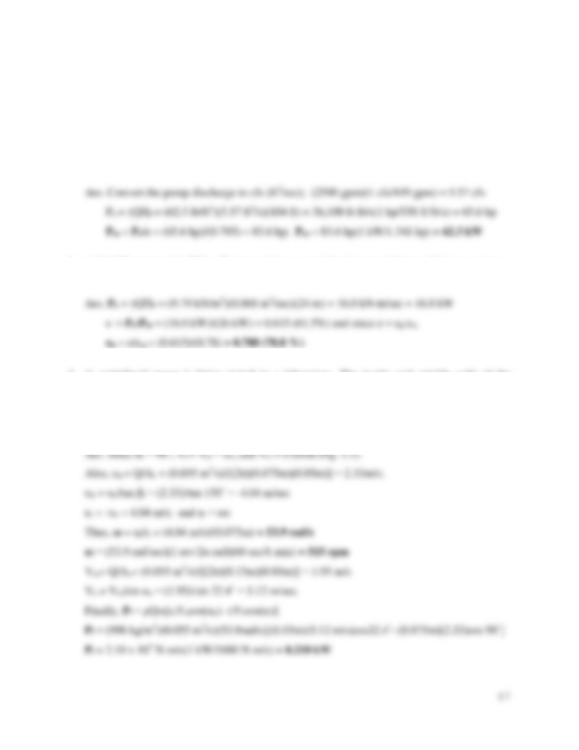
32. Sketch the energy grade line (EGL) and the hydraulic grade line (HGL) for the pump
installation depicted below. Include all factors that impact the cavitation potential of the
pump.
33. Pump specific speed is directly or indirectly dependent on all of the following except
a) friction loss b) pump head c) vapor pressure d) discharge e) rotational speed
34. (T or F) The dimensionless shape number is commonly used in engineering practice to select
or design pumps.
35. If a pump is turning at the rate of 1000 revolutions per minute (rpm), what is its rotational
speed in radians per second?
36. (T or F) Supplying water to high rise buildings requires pumps with low specific speeds.
37. Which pump is the most appropriate for high capacity-low head installations?
a) positive displacement b) centrifugal c) jet (mixed flow) d) propeller e) aquarium pump
38. (T or F) Positive displacement pumps move a lot of water, but can’t overcome much head.
39. Which pump is the most appropriate for low capacity-high head installations?
a) positive displacement b) centrifugal c) jet (mixed flow) d) propeller e) aquarium pump
Pump
47
Problems
1. A centrifugal pump is installed in a pipeline between two reservoirs. The pump is required to
produce a flow rate of 2500 gpm (gallons per minute) in moving water from the lower
reservoir to the upper reservoir. If the water surface elevations of the two reservoirs are
separated by 104 feet, and the pump operates at an overall efficiency of 78.5%, determine the
required power input (in kW) to the motor. (Assume that pipeline losses are negligible.)
2. A 26-kW motor with 78% efficiency drives a centrifugal pump delivery 68 ℓ/sec against a
head of 24 m. Determine the pump efficiency.
3. A centrifugal pump is being tested in a laboratory. The inside and outside radii of the
impeller are 7.5 cm and 15.0 cm respectively. The width of the impeller vanes (or flow
opening height) varies from 5.0 cm at intake to 3.0 cm at outflow. If the measured flow rate
is 55 liters/sec, compute the pump speed (in rpm) and the power input to the pump (in kW).
Assume a shockless entry (αi = 90˚), an exit flow angle (αo) of ββ.4˚, and βi = 150°.
48
4. A centrifugal pump runs at 1800 rpm and has an outside radius of 12 in. (βo = 170º), an inside
radius of 4 in. (βi = 160º), and an impeller thickness (width) of 2 in. at r = ri and 0.75 in. at r
= ro. Determine the pump flow rate for a shockless entry (i.e., αi = 90º), and the exit angle αo.
5. Consider a pump-pipeline system that delivers flow from reservoir A to B with EA = 100 ft and
EB = 120 ft. The pipe has a length of L = 2,800 ft, diameter of D = 2 ft, and a Hazen Williams
coefficient of CHW = 100. The pump characteristics are tabulated below and minor losses (in
feet) accumulate at the rate of 0.01*Q2 where Q is the flow in cfs. Estimate the flow rate in the
pipeline by filling in the solution table below.
Q
Hp
hf
hminor
Hs
HSH
(cfs)
Pump (ft)
(ft)
(ft)
(ft)
(ft)
0
55
10
53
20
47
30
38
40
22
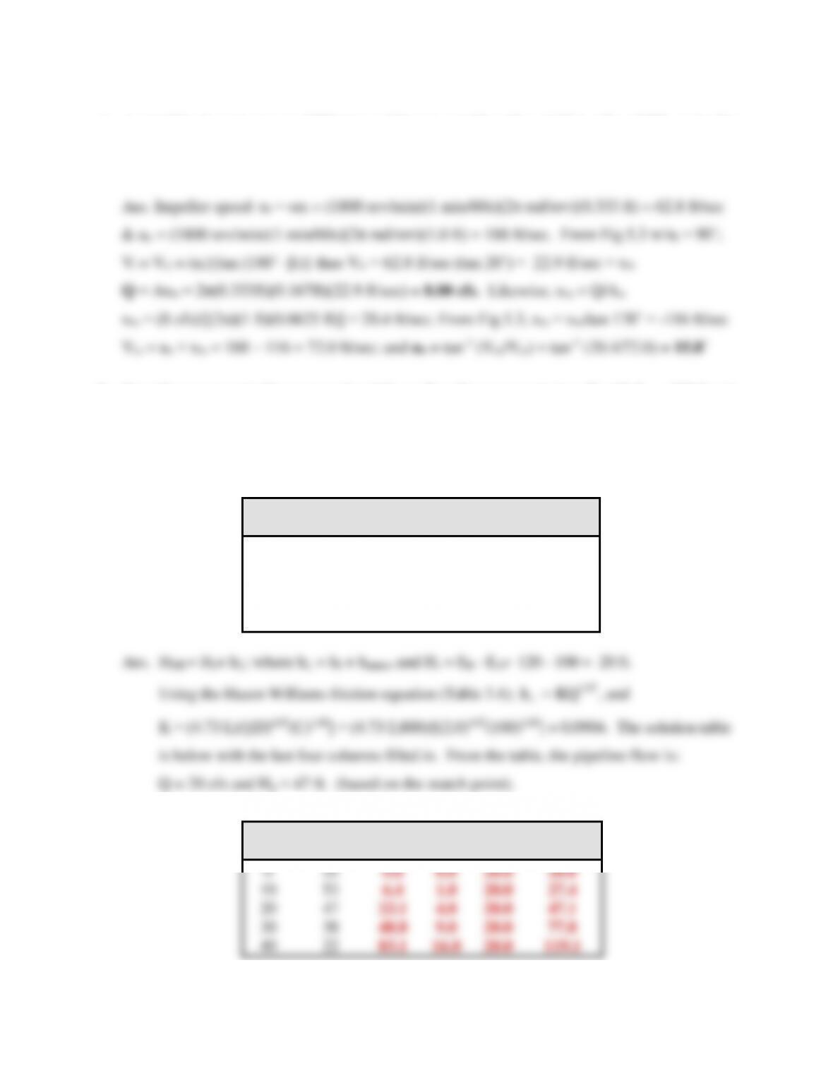
K = (4.7γ∙L)/[(D)4.87(C)1.85] = (4.7γ∙2,800)/[(2.0)4.87(100)1.85] = 0.0904. The solution table
is below with the last four columns filled in. From the table, the pipeline flow is:
Q
Hp
hf
hminor
Hs
HSH
(cfs)
Pump (ft)
(ft)
(ft)
(ft)
(ft)
0
55
0.0
0.0
20.0
20.0
10
53
6.4
1.0
20.0
27.4
20
47
23.1
4.0
20.0
47.1
30
38
48.8
9.0
20.0
77.8
40
22
83.1
16.0
20.0
119.1