26)
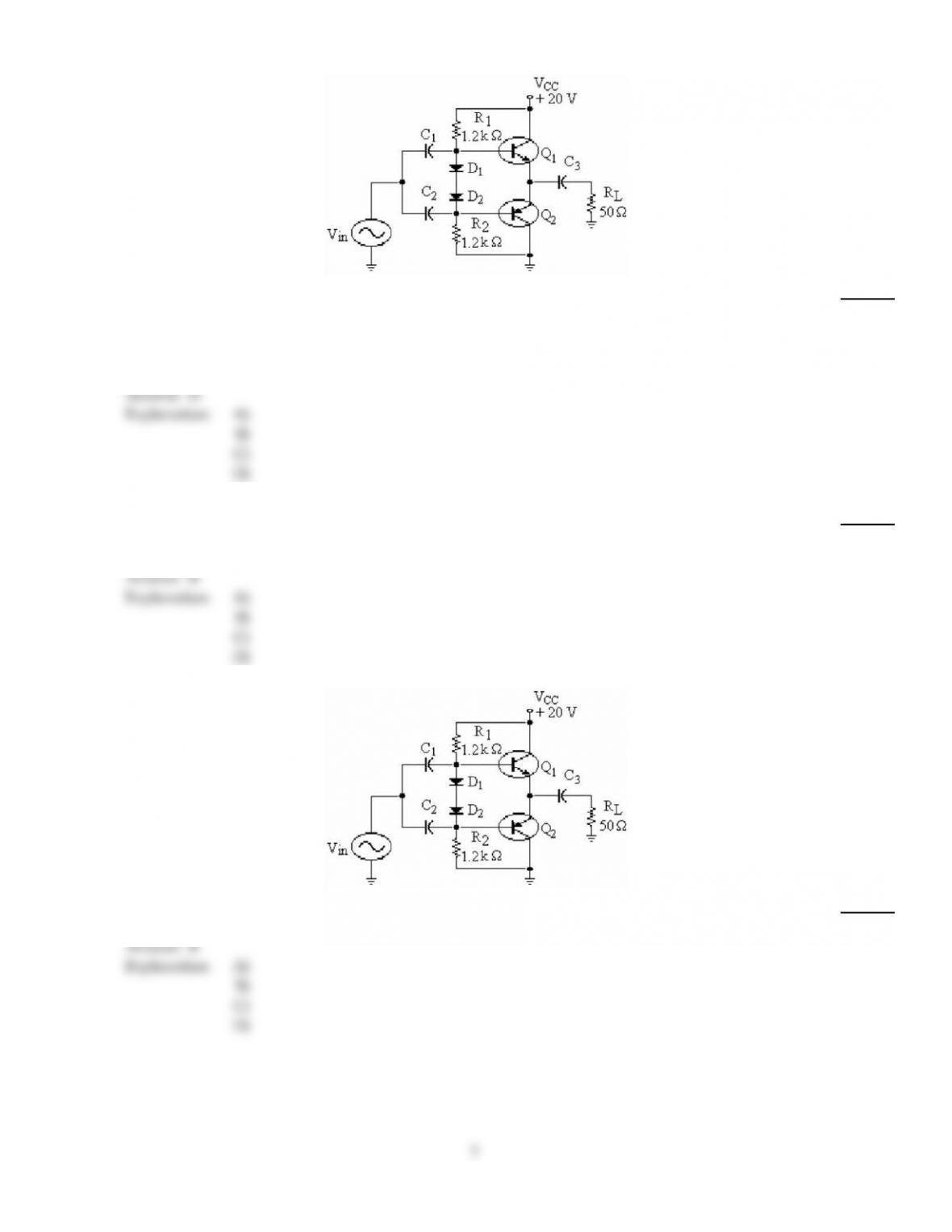
Refer to the figure above. The purpose for the diodes D1 and D2 is
26)
A)
to maintain constant bias with temperature changes.
B)
to allow the correct bias voltages on the two bases.
C)
to apply equal signals to each transistor.
D)
All of the above.
Answer:
D
Explanation:
A)
B)
C)
D)
27)
For a class AB push–pull amplifier, diode bias is used to
27)
A)
ensure thermal runaway.
B)
avoid thermal runaway.
C)
saturate the output transistors.
D)
allow the transistors to conduct for 360°.
Answer:
B
Explanation:
A)
B)
C)
D)
28)
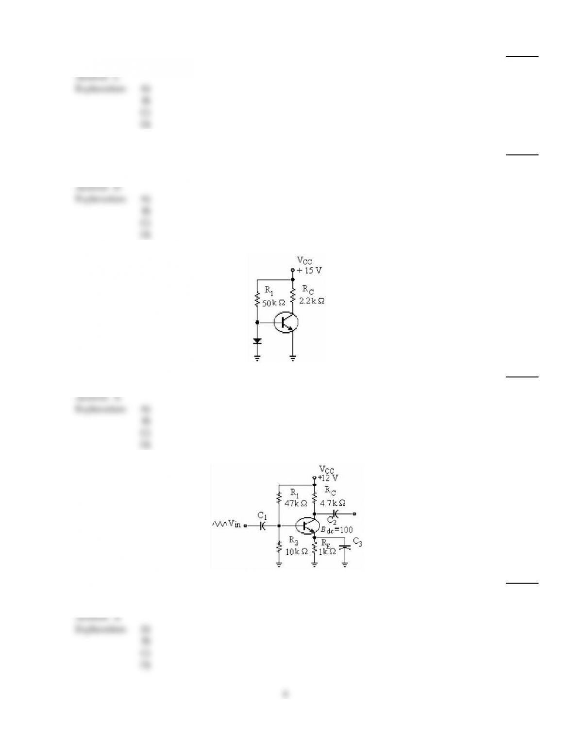
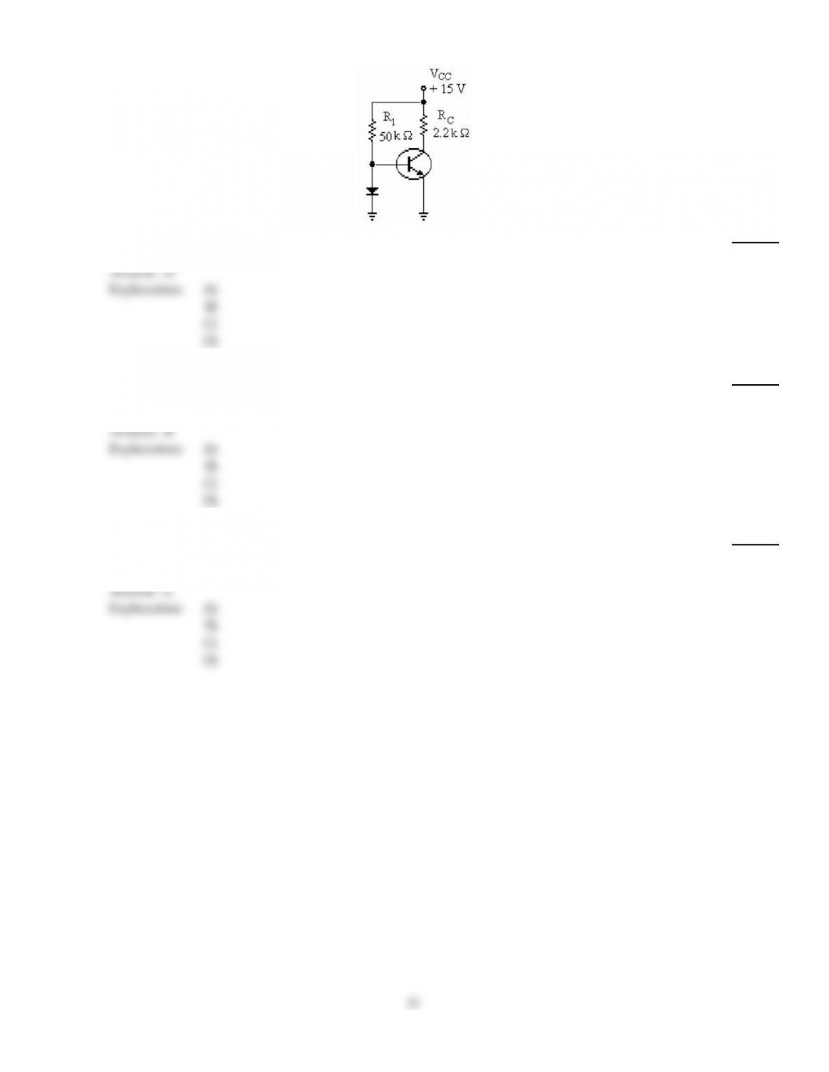
Refer to the figure above. With no signal input, the dc emitter voltage with respect to ground is
28)
A)
10.7 V.
B)
10 V.
C)
9.3 V.
D)
0 V.
Answer:
B
Explanation:
A)
B)
C)
D)
7
29)
The amplifier with the most distortion would be a ________ amplifier.
29)
A)
class A
B)
class B
C)
class C
D)
class AB
Answer:
C
Explanation:
A)
B)
C)
D)
30)
For a class C amplifier, there is collector current for
30)
A)
210° of the input cycle.
B)
360° of the input cycle.
C)
0° of the input cycle.
D)
less than 180° of the input cycle.
Answer:
D
Explanation:
A)
B)
C)
D)
31)
Refer to the figure above. If the diode opened, this amplifier would be operating as
31)
A)
class A.
B)
class B.
C)
class C.
D)
class AB.
Answer:
A
Explanation:
A)
B)
C)
D)
32)
Refer to the figure above. If R1 opened, and Vin at the base was large, Vout at the collector would
32)
A)
distort.
B)
remain the same.
C)
increase.
D)
decrease.
Answer:
A
Explanation:
A)
B)
C)
D)
8
33)
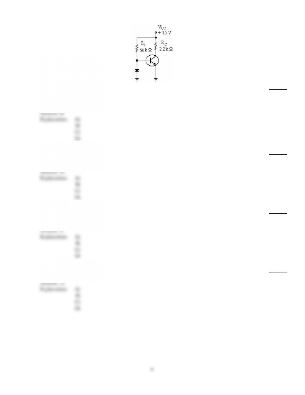
Refer to the figure above. The approximate voltages on the base, collector, and emitter, respectively,
are
33)
A)
0.7 V, 0 V, 15 V.
B)
0.7 V, 15 V, 0 V.
C)
0.7 V, 6.8 V, 0 V.
D)
0 V, 0 V, 0 V.
Answer:
B
Explanation:
A)
B)
C)
D)
34)
The input signal of a class C amplifier
34)
A)
produces brief pulses of collector current.
B)
is negatively clamped at the base.
C)
is amplified and inverted.
D)
All of the above.
Answer:
D
Explanation:
A)
B)
C)
D)
35)
The class of amplifiers that is the most efficient and has the most distortion is class ________
amplifiers.
35)
A)
A
B)
B
C)
C
D)
AB
Answer:
C
Explanation:
A)
B)
C)
D)
36)
A CE amplifier has a load power of 10 mW and the dc power is 215 mW. The efficiency is
36)
A)
4.65%.
B)
25%.
C)
46.5%.
D)
0%.
Answer:
A
Explanation:
A)
B)
C)
D)
9
37)
A class AB amplifier is biased
37)
A)
at the center of the load line.
B)
slightly above the center of the load line.
C)
slightly above cutoff.
D)
at cutoff.
Answer:
C
Explanation:
A)
B)
C)
D)
38)
Refer to the figure above. If there were no output signal, and the measured dc voltage of Q1 emitter
were 0 V, the trouble might be that
38)
A)
R1 is open.
B)
D2 is shorted.
C)
D1 is shorted.
D)
No trouble; everything is normal.
Answer:
A
Explanation:
A)
B)
C)
D)
39)
The quiescent collector current is the same as
39)
A)
ac load resistor current.
B)
ac collector current.
C)
dc collector current.
D)
None of the above.
Answer:
C
Explanation:
A)
B)
C)
D)
40)
When the Q–point is at the center of the ac load line, a maximum ________ signal can be obtained.
40)
A)
class A
B)
class B
C)
class C
D)
None of the above.
Answer:
A
Explanation:
A)
B)
C)
D)
10
41)
Refer to the figure above. The purpose of the diode is to bias the amplifier as
41)
A)
class A.
B)
class B.
C)
class C.
D)
class AB.
Answer:
D
Explanation:
A)
B)
C)
D)
42)
For each transistor in a class B amplifier, there is collector current for
42)
A)
360° of the input cycle.
B)
180° of the input cycle.
C)
270° of the input cycle.
D)
90° of the input cycle.
Answer:
B
Explanation:
A)
B)
C)
D)
43)
For maximum peak–to–peak output voltage, the Q–point should be
43)
A)
near cutoff.
B)
at the center of the dc load line.
C)
at the center of the ac load line.
D)
near saturation.
Answer:
C
Explanation:
A)
B)
C)
D)
11

44)
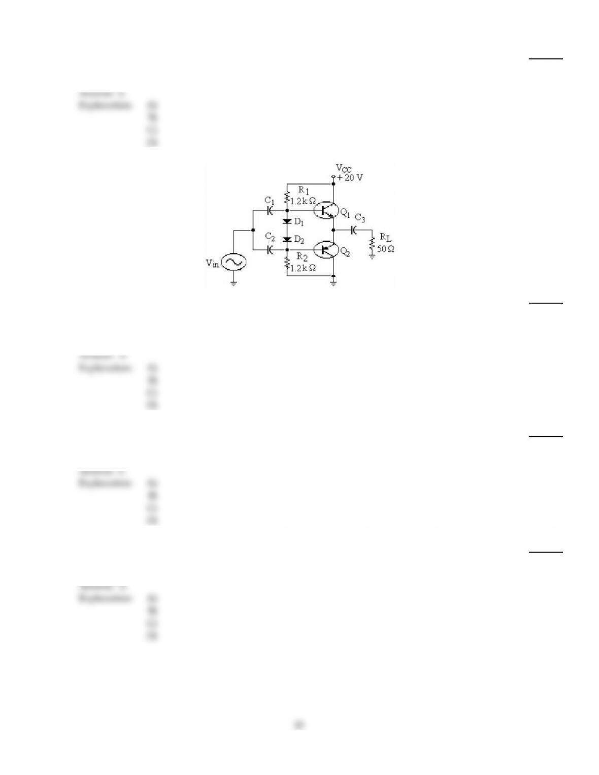
Refer to the figure above. This circuit is operating as a
44)
A)
class A push–pull.
B)
class AB push–pull.
C)
class C push–pull.
D)
class B push–pull.
Answer:
B
Explanation:
A)
B)
C)
D)
45)
Refer to the figure above. If RL shows a zero signal voltage on an oscilloscope, the problem might
be
that
45)
A)
BE2 is open.
B)
C3 is open.
C)
BE1 is open.
D)
R1 is open.
Answer:
B
Explanation:
A)
B)
C)
D)
TRUE/FALSE. Write ‘T’ if the statement is true and ‘F’ if the statement is false.
46)
For certain applications with low–resistance loads, a push–pull amplifier using Darlington
transistors can be used to decrease the input resistance presented to the driving amplifier and avoid
greatly reducing voltage gain.
46)
Answer:
True
False
Explanation:
47)
Darlington pair transistors are often used in power amplifiers because the input impedance is very
low.
47)
Answer:
True
False
Explanation:
48)
The class A amplifier is usually biased below cutoff.
48)
Answer:
True
False
Explanation:
12