Exam
Name___________________________________
MULTIPLE CHOICE. Choose the one alternative that best completes the statement or answers the question.
1)
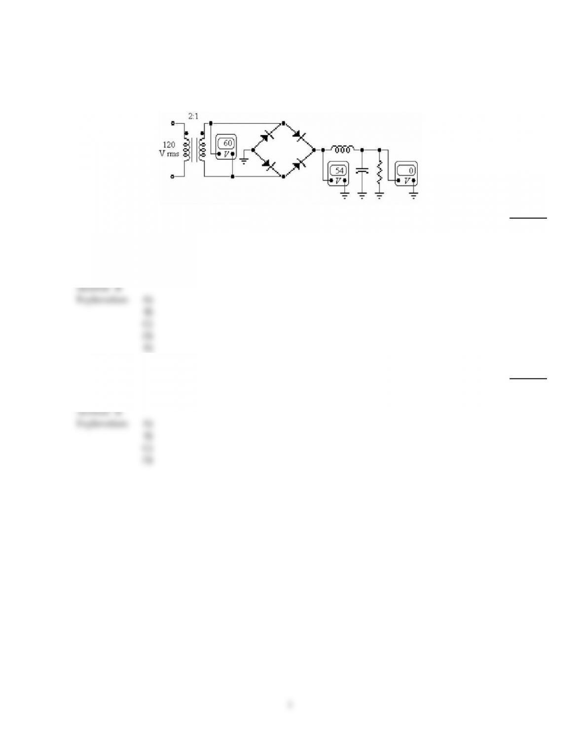
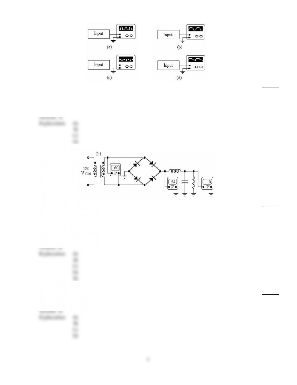
Refer to the figure above. The probable trouble, if any, indicated by these voltages is
1)
A)
an open transformer primary.
B)
the inductor is open.
C)
one of the diodes is open.
D)
an open transformer secondary.
E)
the filter capacitor is open.
Answer:
B
Explanation:
A)
B)
C)
D)
E)
2)
A reverse–biased silicon diode is connected in series with a 12 V source and a resistor. The voltage
across the diode is
2)
A)
0.3 V.
B)
12 V.
C)
0 V.
D)
0.7 V.
Answer:
B
Explanation:
A)
B)
C)
D)
1
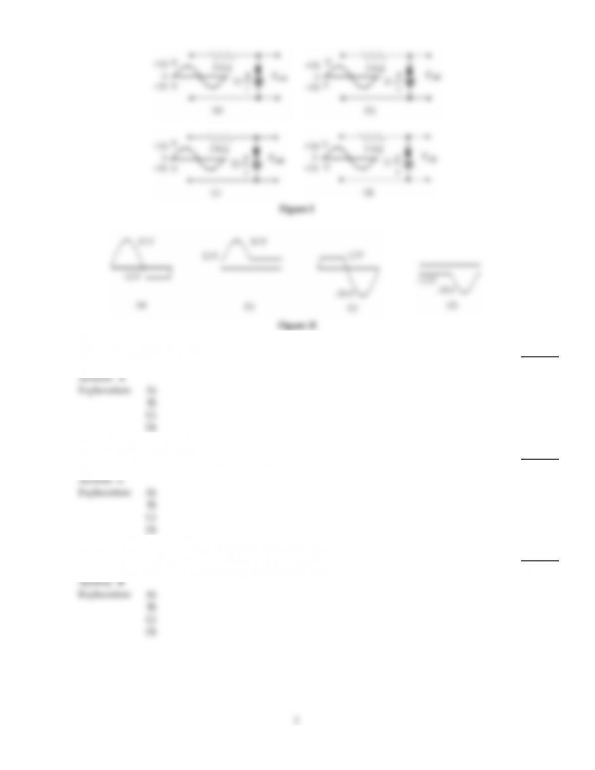
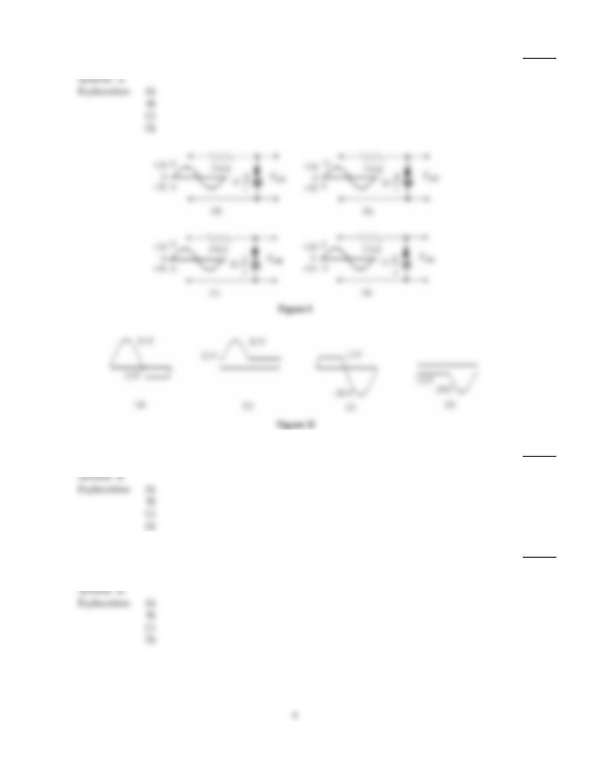
Figure I
Figure II
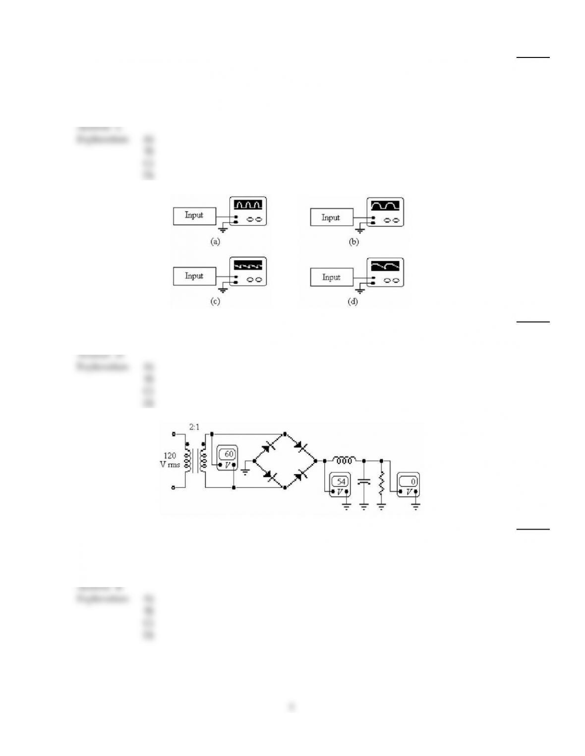
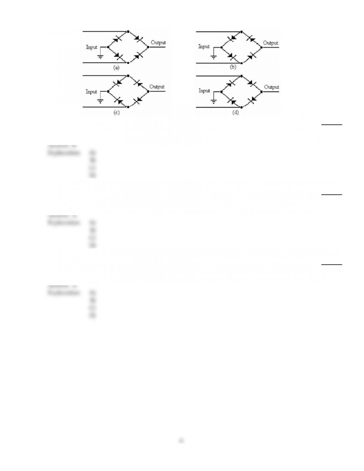
3)
Which of the circuits in Figure I will produce the signal in Figure II (c)?
3)
A)
(a)
B)
(b)
C)
(c)
D)
(d)
Answer:
A
Explanation:
A)
B)
C)
D)
4)
If input frequency is 60 Hz, the output frequency of a bridge rectifier is
4)
A)
240 Hz.
B)
30 Hz.
C)
120 Hz.
D)
60 Hz.
Answer:
C
Explanation:
A)
B)
C)
D)
5)
Another name for a diode limiter is
5)
A)
clamper.
B)
clipper.
C)
dc restorer.
D)
bridger.
Answer:
B
Explanation:
A)
B)
C)
D)
6)
The peak inverse voltage across a nonconducting diode in an unfiltered bridge rectifier equals
approximately
6)
A)
half the peak secondary voltage.
B)
four times the peak value of the secondary voltage.
C)
the peak value of the secondary voltage.
D)
twice the peak secondary voltage.
Answer:
C
Explanation:
A)
B)
C)
D)
7)
A reverse–biased diode has the ________ connected to the positive side of the source, and the
________ connected towards the negative side of the source.
7)
A)
base, anode
B)
anode, cathode
C)
cathode, anode
D)
cathode, base
Answer:
C
Explanation:
A)
B)
C)
D)
8)
When a 60 Hz sinusoidal signal voltage is applied to the input of a half–wave rectifier, the output
frequency is
8)
A)
30 Hz.
B)
60 Hz.
C)
120 Hz.
D)
90 Hz.
Answer:
B
Explanation:
A)
B)
C)
D)
9)
The diode in a half–wave rectifier conducts for ________ of the input cycle.
9)
A)
180°
B)
45°
C)
90°
D)
0°
Answer:
A
Explanation:
A)
B)
C)
D)
10)
The application of a dc voltage to control diode conduction is called
10)
A)
a pn junction.
B)
amplification.
C)
oscillation.
D)
bias.
Answer:
D
Explanation:
A)
B)
C)
D)
3
11)
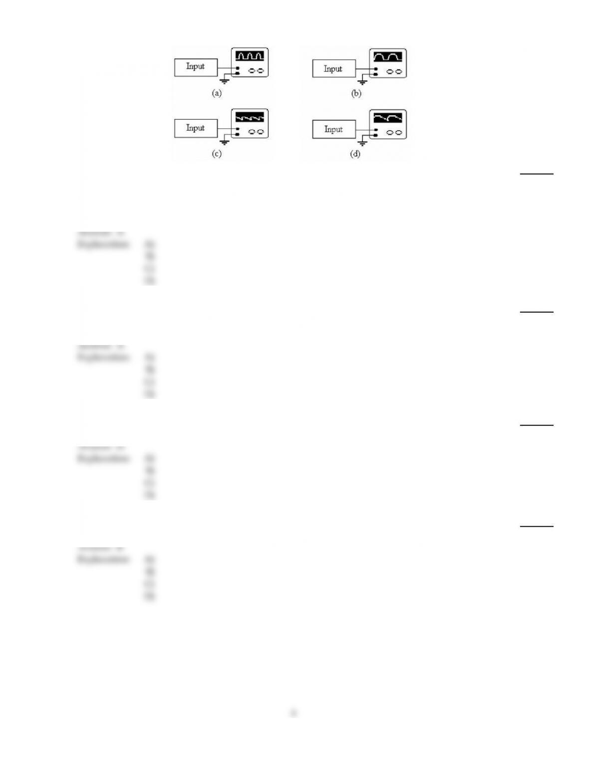
Refer to the figure above. This trace shows the output from
11)
A)
a full–wave filtered rectifier with an open diode.
B)
a half–wave rectifier with no filter.
C)
a full–wave rectifier with no filter and an open diode.
D)
a half–wave rectifier with an open diode.
Answer:
A
Explanation:
A)
B)
C)
D)
12)
The ripple frequency of a bridge rectifier is
12)
A)
double the input frequency.
B)
four times the input frequency.
C)
one–half the input frequency.
D)
the same as the input frequency.
Answer:
A
Explanation:
A)
B)
C)
D)
13)
A typical value of reverse breakdown voltage in a diode is
13)
A)
0.7 V.
B)
0 V.
C)
0.3 V.
D)
50 V or larger.
Answer:
D
Explanation:
A)
B)
C)
D)
14)
A full–wave bridge rectifier uses ________ diode(s) in a bridge circuit.
14)
A)
2
B)
4
C)
1
D)
3
Answer:
B
Explanation:
A)
B)
C)
D)
4
15)
A filtered full–wave rectifier voltage has a smaller ripple than does a half–wave rectifier voltage for
the same load resistance and capacitor values because
15)
A)
the larger the ripple, the better the filtering action.
B)
of the longer time between peaks.
C)
of the shorter time between peaks.
D)
None of the above.
Answer:
C
Explanation:
A)
B)
C)
D)
16)
Refer to the figure above. Which oscilloscope trace indicates the output from a filtered full–wave
rectifier with an open diode?
16)
A)
(a)
B)
(b)
C)
(c)
D)
(d)
Answer:
D
Explanation:
A)
B)
C)
D)
17)
Refer to the figure above. In servicing this power supply, you notice that the ripple voltage is
higher than normal and that the ripple frequency has changed to 60 Hz. The probable trouble is
that
17)
A)
a diode has shorted.
B)
a diode has opened.
C)
the filter capacitor has opened.
D)
the inductor has opened.
Answer:
B
Explanation:
A)
B)
C)
D)
5
18)
Refer to (d) in the figure above. This rectifier arrangement
18)
A)
will produce a negative output voltage.
B)
is incorrectly connected.
C)
will produce a positive output voltage.
D)
None of the above.
Answer:
B
Explanation:
A)
B)
C)
D)
19)
Refer to (c) in the figure above. This rectifier arrangement
19)
A)
will produce a negative output voltage.
B)
is incorrectly connected.
C)
will produce a positive output voltage.
D)
A or C above.
Answer:
A
Explanation:
A)
B)
C)
D)
20)
As the forward current through a forward–biased diode decreases, the voltage across the diode
20)
A)
is relatively constant.
B)
immediately drops to 0 V.
C)
increases and then decreases.
D)
increases.
Answer:
A
Explanation:
A)
B)
C)
D)
6
21)
Refer to the figure above. This oscilloscope trace indicates the output from
21)
A)
a full–wave rectifier with no filter and an open diode.
B)
a full–wave filtered rectifier.
C)
a full–wave filtered rectifier with an open diode.
D)
a half–wave filtered rectifier.
Answer:
A
Explanation:
A)
B)
C)
D)
22)
Refer to the figure above. If the voltmeter across the transformer secondary reads 0 V, the probable
trouble is that
22)
A)
one of the diodes is open.
B)
the transformer secondary is open.
C)
the filter capacitor is open.
D)
the inductor is open.
E)
No trouble exists; everything is normal.
Answer:
B
Explanation:
A)
B)
C)
D)
E)
23)
A voltage regulator compensates for changes in
23)
A)
temperature.
B)
the load conditions.
C)
the input voltage.
D)
All of the above.
Answer:
D
Explanation:
A)
B)
C)
D)
7
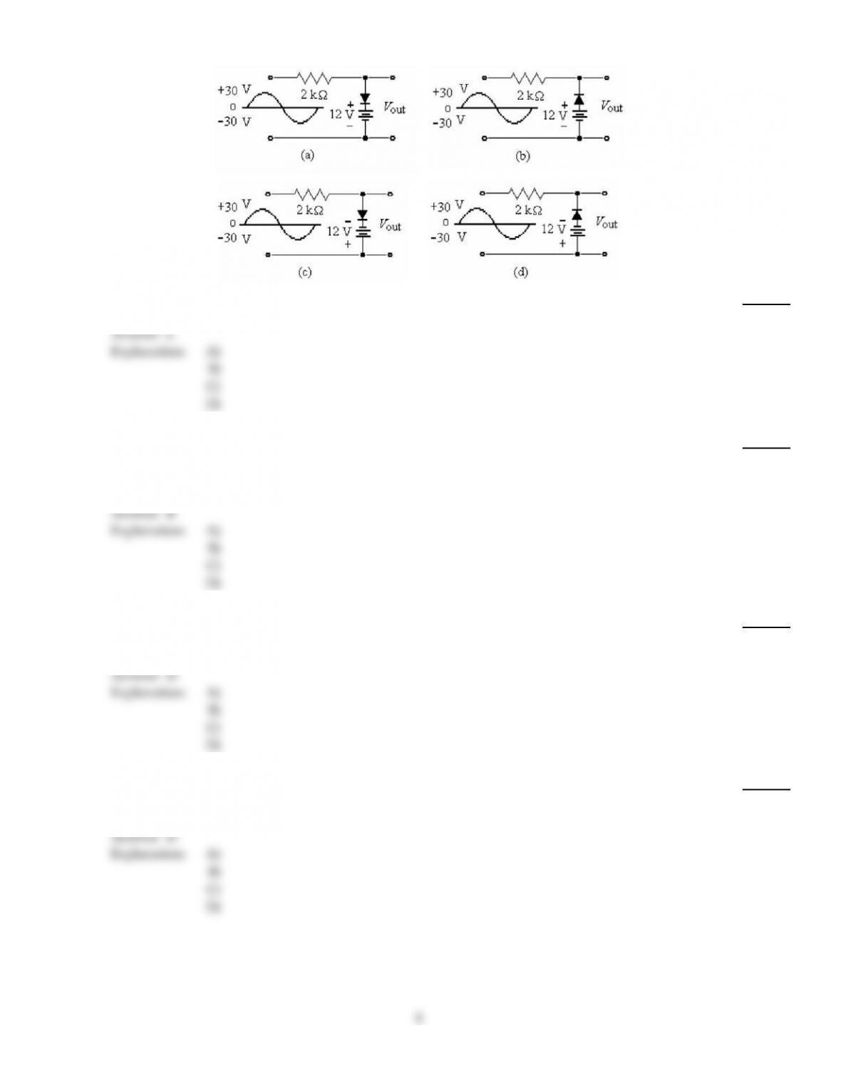
24)
Refer to the figure above. These circuits are known as
24)
A)
amplifiers.
B)
clampers.
C)
clippers.
D)
rectifiers.
Answer:
C
Explanation:
A)
B)
C)
D)
25)
What must be used in series with a forward–biased diode to prevent damage due to excessive
current?
25)
A)
NC switch
B)
Resistor
C)
Ammeter
D)
Nothing is required.
Answer:
B
Explanation:
A)
B)
C)
D)
26)
The knee voltage of a diode is approximately equal to the
26)
A)
reverse voltage.
B)
applied voltage.
C)
breakdown voltage.
D)
barrier potential.
Answer:
D
Explanation:
A)
B)
C)
D)
27)
The dc current through each diode in a bridge rectifier equals
27)
A)
twice the dc load current.
B)
half the dc load current.
C)
one–fourth the dc load current.
D)
the load current.
Answer:
D
Explanation:
A)
B)
C)
D)
8
28)
A typical value of reverse breakdown voltage in a diode is
28)
A)
50 V or larger.
B)
0.7 V.
C)
0.3 V.
D)
0 V.
Answer:
A
Explanation:
A)
B)
C)
D)
Figure I
Figure II
29)
Which of the circuits in Figure I will produce the signal in Figure II (b)?
29)
A)
(a)
B)
(b)
C)
(c)
D)
(d)
Answer:
B
Explanation:
A)
B)
C)
D)
30)
To reduce surge current, ________ should be added to a power supply circuit.
30)
A)
a varactor tuning circuit
B)
additional filter capacitance
C)
a larger fuse
D)
a surge–limiting resistor
Answer:
D
Explanation:
A)
B)
C)
D)
9