25)
The LM317 regulator provides a(n)
25)
A)
adjustable negative output voltage.
B)
fixed negative output voltage.
C)
fixed positive output voltage.
D)
adjustable positive output voltage.
Answer:
D
Explanation:
A)
B)
C)
D)
26)
A voltage regulator with a no–load output dc voltage of 12 V is connect to a load with a resistance
of 10 . If the load resistance decreases to 7.5 , the load voltage will decrease to 10.9 V. The load
current will be ________ and the percent load regulation is ________.
26)
A)
1.45 A, 90.8%
B)
1.6 A, 90.8%
C)
1.6 A, 9.17%
D)
1.45 A, 10.09%
Answer:
D
Explanation:
A)
B)
C)
D)
11
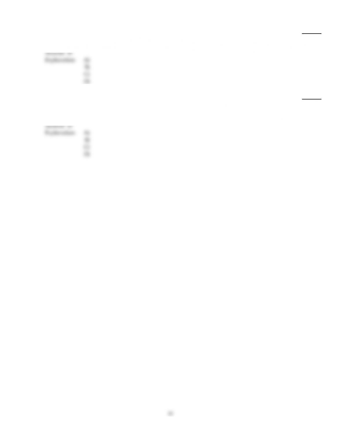
27)
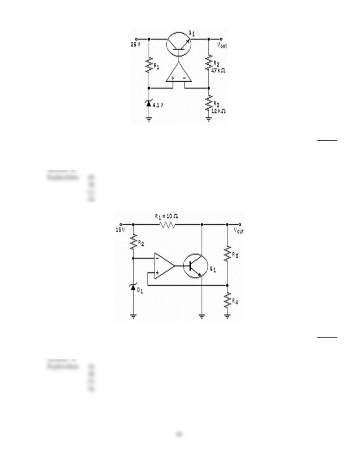
Refer to the figure above. Which of these circuits is known as a series regulator?
27)
A)
(a)
B)
(b)
C)
(c)
D)
None of the above.
Answer:
A
Explanation:
A)
B)
C)
D)
12
28)
Refer to the figure above. The purpose for the op–amp is to
28)
A)
limit the input voltage to the circuit.
B)
amplify the error signal.
C)
supply a reference voltage.
D)
sense the error signal.
Answer:
B
Explanation:
A)
B)
C)
D)
29)
If the load is shorted, the pass transistor has the least power dissipation when the regulator has
29)
A)
a high zener voltage.
B)
low efficiency.
C)
foldback limiting.
D)
buck topology.
Answer:
C
Explanation:
A)
B)
C)
D)
13
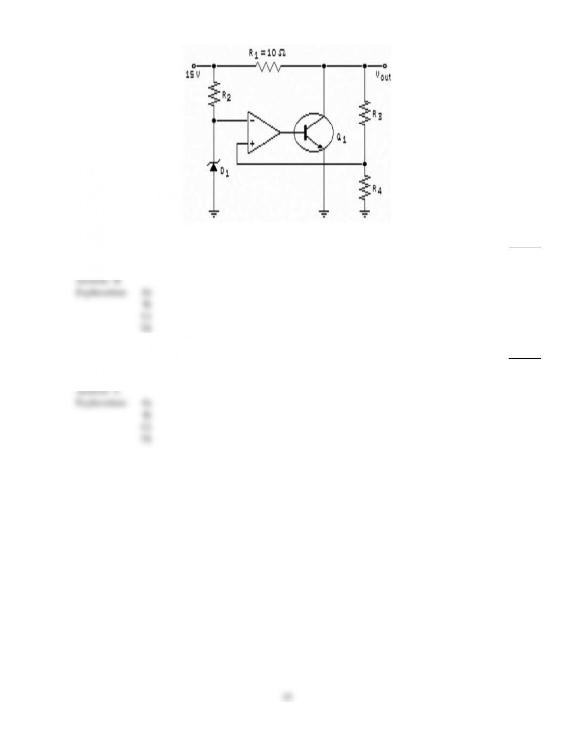
30)
Refer to the figure above. If the output voltage tends to increase due to a decrease in load current,
the transistor will conduct for ________ time each cycle.
30)
A)
exactly half the
B)
the same
C)
a shorter
D)
a longer
Answer:
C
Explanation:
A)
B)
C)
D)
31)
A voltage regulator with a no–load dc output of 15 V is connected to a load with a resistance of 12
. If the load voltage decreases to 14.5 V, the percent regulation would be
31)
A)
3.45%.
B)
3.33%.
C)
100%.
D)
96.7%.
Answer:
A
Explanation:
A)
B)
C)
D)
32)
To get more output voltage from a step–down switching regulator, you have to
32)
A)
increase the duty cycle.
B)
decrease the duty cycle.
C)
decrease the input voltage.
D)
increase the switching frequency.
Answer:
A
Explanation:
A)
B)
C)
D)
14

33)
Refer to the figure above. Which of these circuits is known as a step–up switching regulator?
33)
A)
(a)
B)
(b)
C)
(c)
D)
None of the above.
Answer:
D
Explanation:
A)
B)
C)
D)
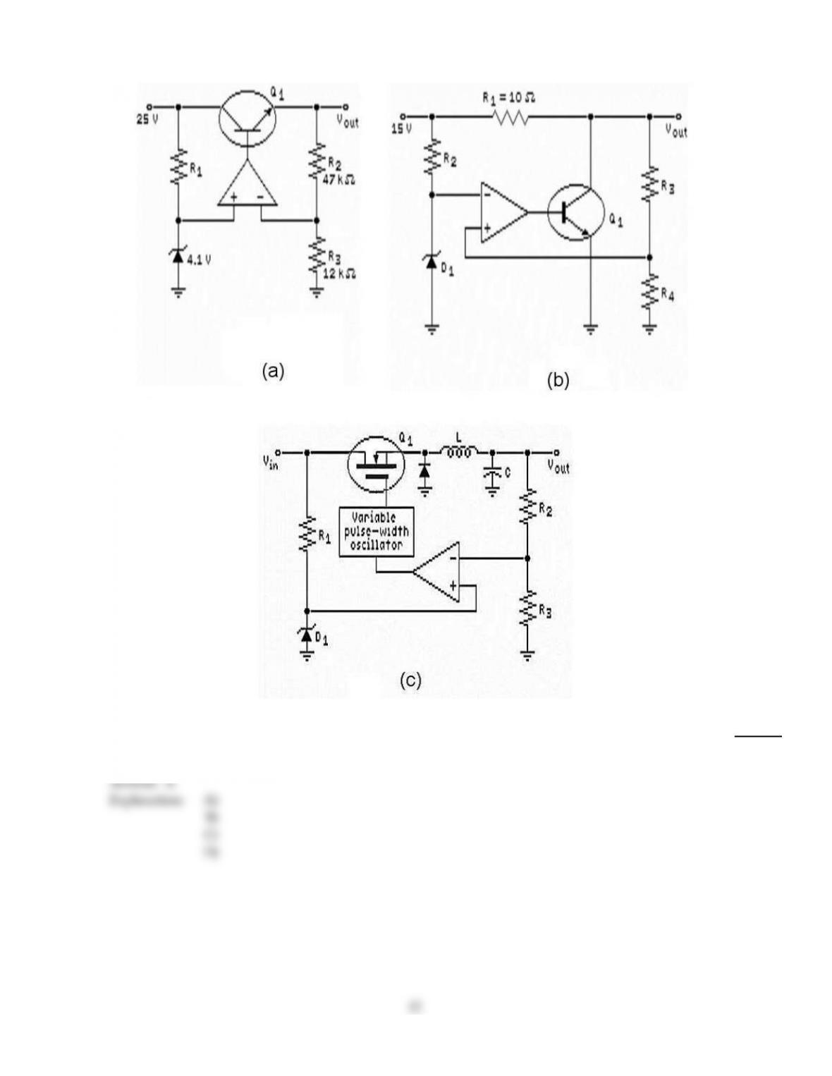
15
34)
Refer to the figure above. If a solder splash shorted the ends of R1 to each other, the result would be
that
34)
A)
the output voltage would not change.
B)
the op–amp would fail.
C)
Q1 would open.
D)
the zener would fail.
Answer:
D
Explanation:
A)
B)
C)
D)
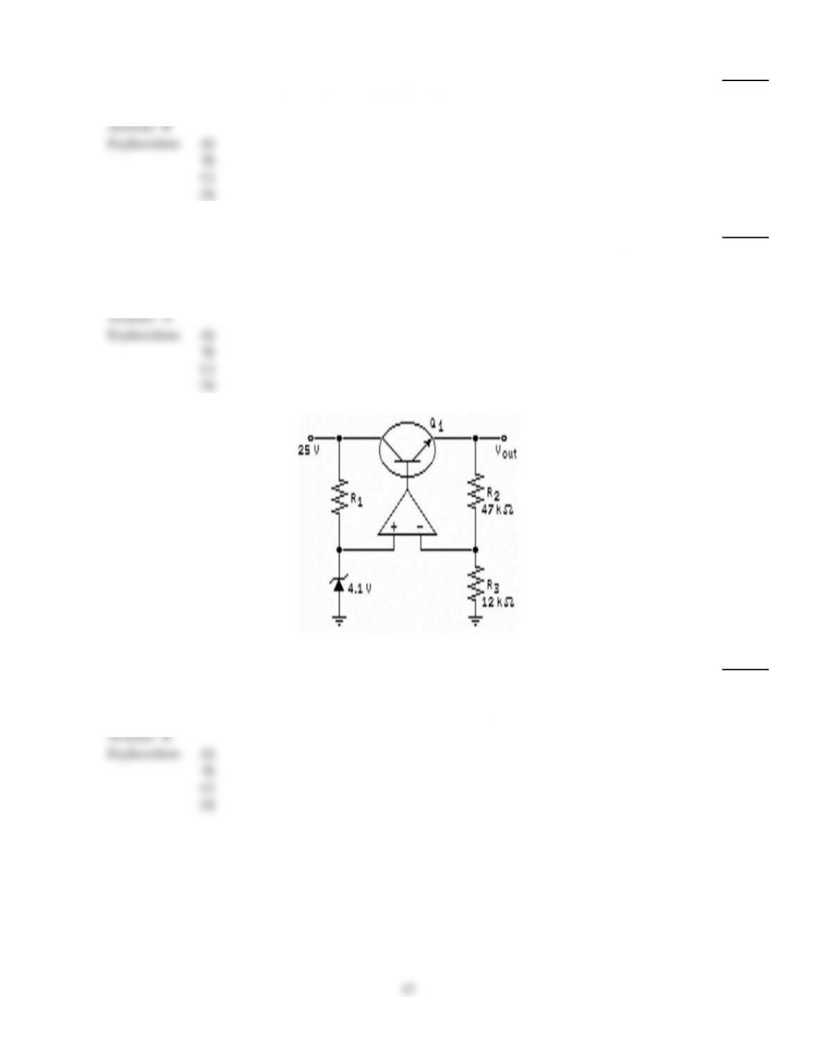
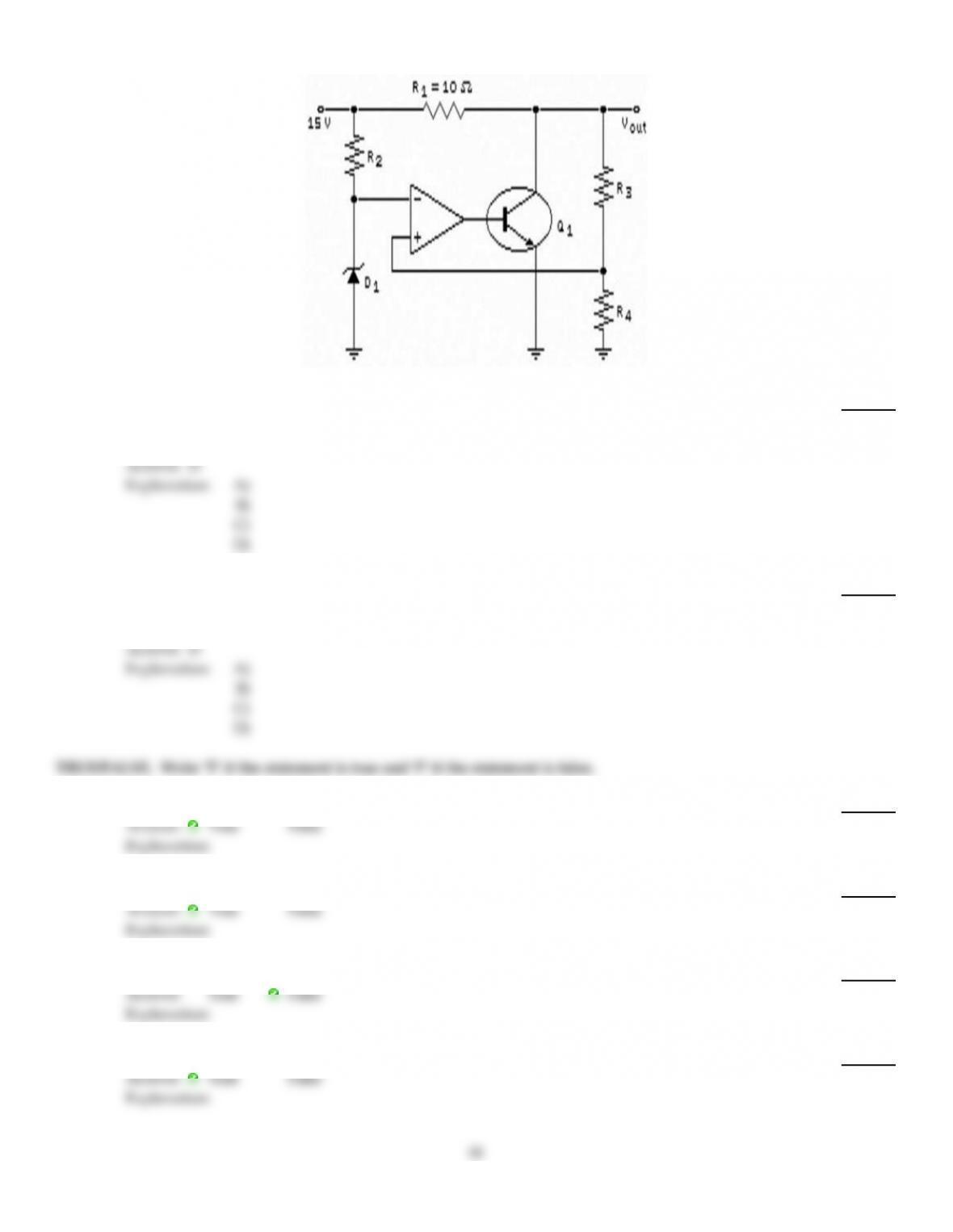
35)
Refer to the figure above. The purpose for the diode D1 is to
35)
A)
supply a reference voltage.
B)
amplify the error signal.
C)
limit the input voltage to the circuit.
D)
sense the error signal.
Answer:
A
Explanation:
A)
B)
C)
D)
16
36)
With foldback current limiting, the load voltage approaches zero, and the load current approaches
36)
A)
infinity.
B)
a small value.
C)
the zener current.
D)
a destructive level.
Answer:
B
Explanation:
A)
B)
C)
D)
37)
An increase of line voltage into a power supply usually produces
37)
A)
an increase in load voltage.
B)
less power dissipation in the rectifier diodes.
C)
a decrease in load resistance.
D)
a decrease in efficiency.
Answer:
A
Explanation:
A)
B)
C)
D)
38)
Refer to the figure above. This circuit is brought in for repair. The measured output voltage was 25
V under all load conditions. A possible cause of this symptom might be that
38)
A)
Vin has decreased.
B)
R2 has opened.
C)
R3 has opened.
D)
Q1 base–emitter has opened.
Answer:
B
Explanation:
A)
B)
C)
D)
17
39)
Refer to the figure above. An increase in VOUT will cause Q1 to
39)
A)
conduct more.
B)
conduct the same.
C)
open.
D)
conduct less.
Answer:
D
Explanation:
A)
B)
C)
D)
40)
If the output of a voltage regulator varies from 20 to 19.8 V when the line voltage varies over its
specified range, the load regulation is
40)
A)
0.
B)
5%.
C)
2%.
D)
1%.
Answer:
D
Explanation:
A)
B)
C)
D)
TRUE/FALSE. Write ‘T’ if the statement is true and ‘F’ if the statement is false.
41)
Most voltage regulators include some kind of protection circuitry.
41)
Answer:
True
False
Explanation:
42)
A zener diode is sometimes used as a voltage regulator.
42)
Answer:
True
False
Explanation:
43)
In a shunt regulator, the control element is in series with the load.
43)
Answer:
True
False
Explanation:
44)
Switching regulators are very efficient.
44)
Answer:
True
False
Explanation:
18

45)
Line regulation is the percentage change in input voltage for a given change in output voltage.
45)
Answer:
True
False
Explanation:
19