24)
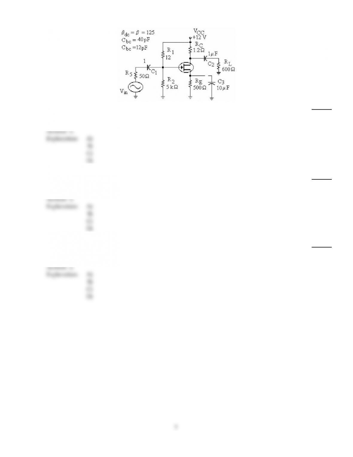
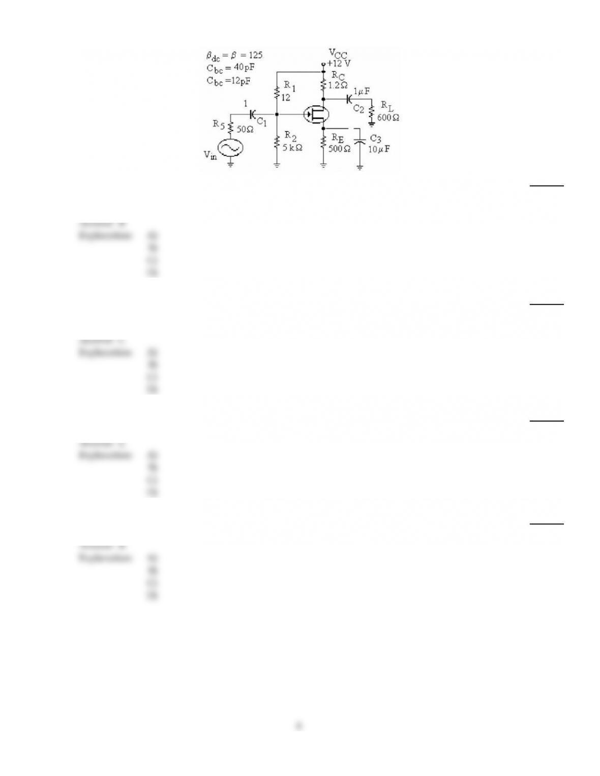
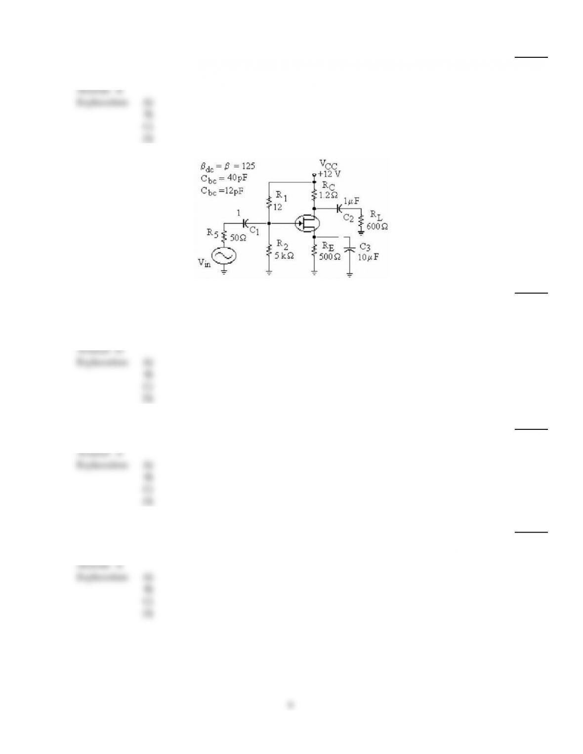
Refer to the figure above. Low frequency response is affected by
24)
A)
CBE.
B)
RC.
C)
C3.
D)
All of the above.
Answer:
C
Explanation:
A)
B)
C)
D)
25)
If an amplifier has a voltage gain of 54 dB, and an input signal of 22 mV, the output signal voltage
would be
25)
A)
55.3 V.
B)
24.5 V.
C)
11 V.
D)
2.45 V.
Answer:
C
Explanation:
A)
B)
C)
D)
26)
If an amplifier has an input signal voltage of 0.37 mV and an output voltage of 16.8 V, the voltage
gain in dB would be
26)
A)
46.6 dB.
B)
45.4 dB.
C)
93.1 dB.
D)
33.1 dB.
Answer:
C
Explanation:
A)
B)
C)
D)
7
27)
Refer to the figure above. The reduction in the output at very high frequencies is due to
27)
A)
the positive feedback effect of VBE.
B)
the negative feedback effect of Cbc.
C)
RL decreasing in value.
D)
the negative feedback effect of RE.
Answer:
B
Explanation:
A)
B)
C)
D)
28)
Refer to the figure above. If the output voltage at fcl is 12 mV, the actual output voltage at the
midpoint frequency would be
28)
A)
12 mV.
B)
8.48 mV.
C)
16.97 mV.
D)
12 mVp–p.
Answer:
C
Explanation:
A)
B)
C)
D)
29)
Phase shift in the input of an RC circuit will approach 90° when frequency approaches
29)
A)
mid–range.
B)
cutoff.
C)
zero.
D)
maximum.
Answer:
C
Explanation:
A)
B)
C)
D)
30)
If the voltage gain doubles, the decibel voltage gain increases by
30)
A)
6 dB.
B)
3 dB.
C)
a factor of 2.
D)
10 dB.
Answer:
B
Explanation:
A)
B)
C)
D)
8
31)
A high pass filter may be used to
31)
A)
pass high frequencies.
B)
pass frequencies between low and high.
C)
pass low frequencies.
D)
Both A and B above.
Answer:
A
Explanation:
A)
B)
C)
D)
32)
Refer to the figure above. The bandwidth of this amplifier is
32)
A)
the lower frequency times 0.707.
B)
the upper frequency divided by 0.707.
C)
the sum of the upper and lower frequencies.
D)
the difference between the upper and lower frequencies.
Answer:
D
Explanation:
A)
B)
C)
D)
33)
Refer to the figure above. A definite reduction in the output voltage is noticed. The trouble is that
33)
A)
C3 has opened.
B)
C3 has shorted.
C)
C1 has opened.
D)
C2 has opened.
Answer:
A
Explanation:
A)
B)
C)
D)
34)
If an amplifier has a bandwidth of 47 kHz and a higher cutoff frequency of 104 kHz, the lower
cutoff frequency would be
34)
A)
57 kHz.
B)
47 kHz.
C)
104 kHz.
D)
151 kHz.
Answer:
A
Explanation:
A)
B)
C)
D)
9

35)
The voltage gain of an amplifier is 150. If the output voltage doubles (for the same amount of input
voltage), the voltage gain equals
35)
A)
49.5 db.
B)
21.7 db.
C)
43.5 db.
D)
114 db.
Answer:
A
Explanation:
A)
B)
C)
D)
36)
The voltage gain of an amplifier is 200. The decibel voltage gain is
36)
A)
46 dB.
B)
106 dB.
C)
23 dB.
D)
200 dB.
Answer:
A
Explanation:
A)
B)
C)
D)
37)
A Bode plot
37)
A)
indicates voltage gain only at 0 Hz.
B)
indicates voltage gain with no reference to frequency.
C)
provides a visual presentation of decibel voltage gain vs. frequency.
D)
is a testing method used for dc amplifiers.
Answer:
C
Explanation:
A)
B)
C)
D)
38)
What effect does low frequency have on the emitter bypass RC circuit?
38)
A)
Increases impedance and increases voltage gain
B)
Decreases impedance and decreases voltage gain
C)
Decreases impedance and increases voltage gain
D)
Increases impedance and decreases voltage gain
Answer:
D
Explanation:
A)
B)
C)
D)
39)
For a lag network above the cutoff frequency, the voltage gain
39)
A)
decreases at the rate of 20 db per decade.
B)
increases at the rate of 6 db per octave.
C)
decreases at the rate of 6 db per octave.
D)
A and C above.
Answer:
D
Explanation:
A)
B)
C)
D)
10
TRUE/FALSE. Write ‘T’ if the statement is true and ‘F’ if the statement is false.
40)
At the cutoff frequency, the output is down by 3 dB.
40)
Answer:
True
False
Explanation:
41)
High–frequency response is limited by the internal capacitances of a transistor.
41)
Answer:
True
False
Explanation:
42)
Coupling and bypass capacitors limit the low–frequency response of an amplifier.
42)
Answer:
True
False
Explanation:
43)
An octave of frequency is a ten–times change.
43)
Answer:
True
False
Explanation:
44)
To effectively analyze an RC coupled amplifier’s high frequency response, you only need to
consider the coupling and bypass capacitances. The internal capacitance can be ignored.
44)
Answer:
True
False
Explanation:
45)
The bandwidth is the sum of the two cutoff frequencies.
45)
Answer:
True
False
Explanation:
11