Page 1 of 25
Transducers & Sensors
Shashidharan p, Former HOD, Dept. of Physics, Vartak College
Transducer is a device that converts energy from one form to another. Usually a transducer
converts a signal in one form of energy to a signal in another. Transducers are often
employed at the boundaries of automation, measurement and control systems, where
electrical signals are converted to and from other physical quantities (energy, force, torque,
light, motion, position, etc.). The process of converting one form of energy to another is
known as transduction.
Transducers can be categorized by which direction information passes through them:
Sensor is a transducer that receives and responds to a signal or stimulus from a physical
system. It produces a signal, which represents information about the system, which is used
by some type of telemetry, information or control system.
Actuator is a device that is responsible for moving or controlling a mechanism or system. It
is controlled by a signal from a control system or manual control. It is operated by a source of
energy, which can be mechanical force, electrical current, hydraulic fluid pressure, or
pneumatic pressure, and converts that energy into motion. An actuator is the mechanism by
which a control system acts upon an environment. The control system can be simple (a fixed
mechanical or electronic system), software –based (e.g. a printer driver, robot control system),
a human, or any other input.
Bidirectional transducers convert physical phenomena to electrical signals and also convert
electrical signals into physical phenomena. An example of an inherently bidirectional
transducer is an antenna, which can convert radio waves (EM waves) into an electrical signal
to be processed by a radio receiver, or translate an electrical signal from a transmitter into
radio waves. Another example is voice coils, which are used in loudspeakers to translate an
electrical signal into sound and in dynamic microphones to translate sound waves into an
electrical signal.
Passive sensors require an external power source to operate, which is called an excitation
signal. The signal is modulated by the sensor to produce an output signal. For example,
a thermistor does not generate any electrical signal, but by passing an electric current through
it, its resistance can be measured by detecting variations in the current or voltage across the
thermistor.
Active sensors, in contrast, generate an electric current in response to an external stimulus
which serves as the output signal without the need of an additional energy source. Such
examples are a PV cell, piezoelectric sensor, thermocouple etc.
Some specifications that are used to rate transducers
Dynamic Range: This is the ratio between the largest amplitude signal and the smallest
amplitude signal the transducer can effectively translate. Transducers with larger dynamic
range are more “sensitive” and precise.
Repeatability: This is the ability of the transducer to produce an identical output when
stimulated by the same input.
Noise: All transducers add some random noise to their output. In electrical transducers this
may be electrical noise due to thermal motion of charges in circuits. Noise corrupts small
signals more than large ones.
Hysteresis: This is a property in which the output of the transducer depends not only on its
current input but its past input. For example, an actuator which uses a gear train may have
some backlash, which means that if the direction of motion of the actuator reverses, there will
be a dead zone before the output of the actuator reverses, caused by play between the gear
teeth.
Page 2 of 25
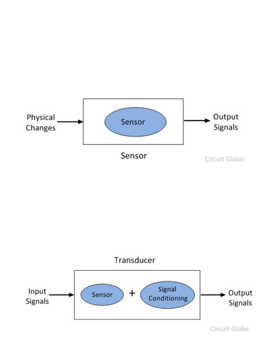
Difference between Sensor & Transducer
One of the significant difference between the sensor and the transducer is that the sensor
senses the physical changes occur in the surrounding whereas the transducer converts the
physical quantity or nonelectrical into another signal or electrical signal.
Definition of Sensor
The sensor is a device that measures the physical quantity (i.e. Heat, light, sound, etc.) into an
easily readable signal (voltage, current etc.). It gives accurate readings after calibration.
Examples – The mercury used in the thermometer converts the measurand temperature into
an expansion and contraction of the liquid which is easily measured with the help of a
calibrated glass tube. The thermocouple also converts the temperature to an output voltage
which is measured by the thermometer.
The sensors have many applications in the electronics equipment. The few of them are
explained below.
The motion sensors are used in the home security system and the automation door system.
The photo sensor senses the infrared or ultraviolet light.
The accelerometer sensor use in the mobile for detecting the screen rotations.
Definition of Transducer
The transducer is a device that changes the physical attributes of the non–electrical signal into
an electrical signal which is easily measurable. The process of energy conversion in the
transducer is known as the transduction. The transduction is completed into two steps. First
by sensing the signal and then strengthening it for further processing.
The transducer has three major components; they are the input device, signal conditioning or
processing device and an output device.
The input devices receive the measurand quantity and transfer the proportional analogue
signal to the conditioning device. The conditioning device modify, filter or attenuates the
signal which is easily acceptable by the output devices.
The following are the differences between the sensor and transducer.
The sensor senses the physical change across the surrounding whereas the transducer
transforms the one form of energy into another.
Page 3 of 25
The sensor itself is the major component of the sensor, whereas the sensor and the signal
conditioning are the major elements of the transducer.
The primary function of the sensor is to sense the physical changes, whereas the transducer
converts the physical quantities into an electrical signal.
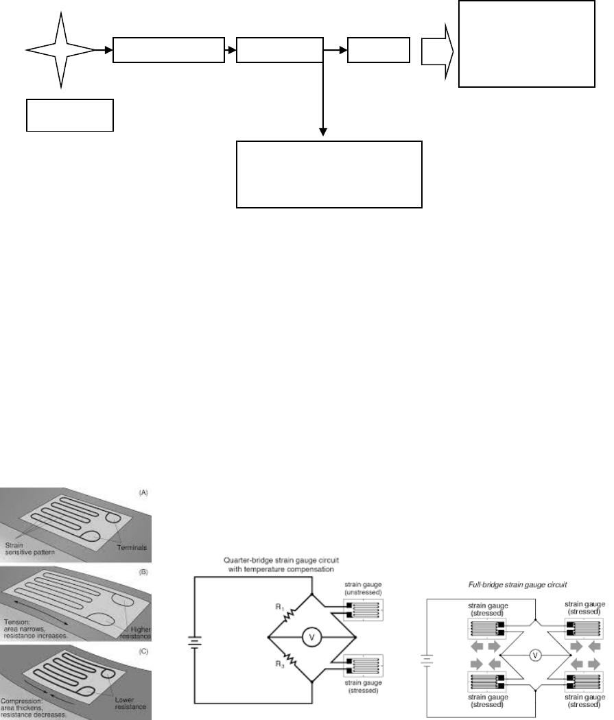
When a physical quantity has to be measured, an appropriate sensor has to be used. If the
output of the sensor is weak, an amplifier should be used to amplify the signal. This in turn
amplifies not only the required signal but also stray signals called “NOISE”. Hence filters are
used to remove this noise and allow only the required signal to appear for measurement
purpose. Using instruments like voltmeter, CRO etc this amplified signal can be measured.
Strain gauge: is a device used to measure strain on an object. Invented by Edward E.
Simmons and Arthur C. Ruge in 1938, the most common type of strain gauge consists of
an insulating flexible backing which supports a metallic foil pattern. The gauge is attached to
the object by a suitable adhesive, such as cyanoacrylate. As the object is deformed, the foil is
deformed, causing its electrical resistance to change. This resistance change, usually
measured using a Wheatstone Bridge, is related to the strain by the quantity known as
the Gauge Factor (GF).
A strain gauge takes advantage of the physical property of electrical conductance and its
dependence on the conductor’s geometry. When an electrical conductor is stretched within the
limits of its elasticity such that it does not break or permanently deform, it will become
narrower and longer, which increases its electrical resistance end-to–end. Conversely, when a
conductor is compressed such that it does not buckle, it will broaden and shorten, which
decreases its electrical resistance end–to-end. From the measured electrical resistance of the
strain gauge, the amount of induced stress may be inferred (Fig.1).
Fig.1 Fig.1a Fig.1b
S
SENSOR
AMPLIFIER
FILTER
ADC
PROCESSOR
SYSTEM FOR
DATA
AMPLIFIEDANALOG
SIGNAL FOR
MEASUREMENT

Page 4 of 25
A typical strain gauge arranges a long, thin conductive strip in a zigzag pattern of parallel
lines. This does not increase the sensitivity, since the percentage change in resistance for a
given strain for the entire zigzag is the same as for any single trace. A single linear trace
would have to be extremely thin, hence liable to overheating (which would change its
resistance and cause it to expand), or would need to be operated at a much lower voltage,
making it difficult to measure resistance changes accurately.
The gauge factor GF is defined as: GF = (ΔR/Rg)/ε where ΔR is the change in resistance
caused by strain, Rg is the un–deformed gauge resistance, and ε is strain.
For common metallic foil gauges, the gauge factor is usually a little over 2. For a single
active gauge and three dummy resistors of the same resistance about the active gauge in a
balanced Wheatstone Bridge configuration, the output sensor voltage SV from the full bridge
is approximately: SV = EV*GF*ε where EV is the bridge excitation voltage. Fig.1a & Fig.1b
shows two bridge configuration called quarter bridge and full bridge.
Foil gauges typically have active areas of about 2–10 mm2 in size. With careful installation,
the correct gauge, and the correct adhesive, strains up to at least 10% can be measured.
An excitation voltage is applied to input leads of the gauge network, and a voltage reading is
taken from the output leads. Typical input voltages are 5V or 12V and typical output readings
are in milli volts.
Strain gauges are attached to the substrate with special glue. The type of glue depends on the
required lifetime of the measurement system. For short term measurements (up to some
weeks) cyanoacrylate glue is appropriate, for long lasting installation epoxy glue is required.
Usually epoxy glue requires high temperature curing (at about 80-100°C). The preparation of
the surface where the strain gauge is to be glued is of the utmost importance. The surface
must be smoothed (e.g. with very fine sand paper), de-oiled with solvents, the solvent traces
must then be removed and the strain gauge must be glued immediately after this to avoid
oxidation or pollution of the prepared area. If these steps are not followed the strain gauge
binding to the surface may be unreliable and unpredictable measurement errors may be
generated.
Variations in temperature will cause a multitude of effects. The object will change in size by
thermal expansion, which will be detected as a strain by the gauge. Resistance of the gauge
will change, and resistance of the connecting wires will change.
Most strain gauges are made from a constantan alloy (A-alloy). Various constantan alloys and
Karma alloys (K-alloy) have been designed so that the temperature effects on the resistance
of the strain gauge itself largely cancel out the resistance change of the gauge due to the
thermal expansion of the object under test.
Strain gauges that are not self–temperature-compensated [such as isoelastic (D alloy) alloy]
can be temperature compensated by use of the dummy gauge technique. A dummy gauge
(identical to the active strain gauge) is installed on an unstrained sample of the same material
as the test specimen. The sample with the dummy gauge is placed in thermal contact with the
test specimen, adjacent to the active gauge. The dummy gauge is wired into a Wheatstone
Bridge on an adjacent arm to the active gauge so that the temperature effects on the active
and dummy gauges cancel each other. (Murphy’s Law was originally coined in response to a
set of gauges being incorrectly wired into a Wheatstone bridge).
Errors and compensations
Zero Offset: If the impedance of the four gauge arms are not exactly the same after bonding
the gauge to the force collector, there will be a zero offset which can be compensated by
Page 5 of 25
introducing a parallel resistor to one or more of the gauge arms.
Temperature coefficient of gauge factor (TCGF): is the change of sensitivity of the device
to strain with change in temperature. This is generally compensated for by the introduction of
a fixed resistance in the input leg, whereby the effective supplied voltage will decrease with a
temperature increase, compensating for the increase in sensitivity with the temperature
increase. This is known as modulus compensation in transducer circuits. As the temperature
rises the load cell element becomes more elastic and therefore under a constant load will
deform more and lead to an increase in output; but the load is still the same. The clever bit in
all this is that the resistor in the bridge supply must be a temperature sensitive resistor that is
matched to both the material to which the gauge is bonded and also to the gauge element
material. The value of that resistor is dependent on both of those values and can be
calculated. In simple terms, if the output increases then the resistor value also increase
thereby reducing the net voltage to the transducer. Get the resistor value right and you will
see no change.
Zero shift with temperature: If the TCGF of each gauge is not the same, there will be a zero
shift with temperature. This is also caused by anomalies in the force collector. This is usually
compensated for with one or more resistors strategically placed in the compensation network.
Linearity is an error whereby the sensitivity changes across the pressure range. This is
commonly a function of the force collection thickness selection for the intended pressure and
the quality of the bonding.
Hysteresis: is an error of return to zero after pressure excursion.
Repeatability: This error is sometimes tied-in with hysteresis but is across the pressure
range.
EMI induced errors: As strain gauges output voltage is in the mV range, even μV if the
Wheatstone bridge voltage drive is kept low to avoid self heating of the element, special care
must be taken in output signal amplification to avoid amplifying also the superimposed noise.
A solution which is frequently adopted is to use “carrier frequency” amplifiers which convert
the voltage variation into a frequency variation (as in VCOs) and have a narrow bandwidth
thus reducing out of band EMI.
Overloading: If a strain gauge is loaded beyond its design limit (measured in microstrain) its
performance degrades and cannot be recovered. Normally good engineering practice suggests
not to stress strain gauges beyond ±3000 microstrain.
Humidity: If the wires connecting the strain gauge to the signal conditioner are not protected
against humidity, such as bare wire, corrosion can occur, leading to parasitic resistance. This
can allow currents to flow between the wires and the substrate to which the strain gauge is
glued, or between the two wires directly, introducing an error which competes with the
current flowing through the strain gauge. For this reason, high-current, low–resistance strain
gauges (120 ohm) are less prone to this type of error. To avoid this error it is sufficient to
protect the strain gauges wires with insulating enamel (e.g., epoxy or polyurethane type).
Strain gauges with unprotected wires may be used only in a dry laboratory environment but
not in an industrial one.
Non–contact strain measurements
Strain can also be measured using Digital Image Correlation (DIC). With this technique one
or two cameras are used in conjunction with a DIC software to track features on the surface
of components to detect small motion. The full strain map of the tested sample can be
calculated, providing similar display as a Finite Element Analysis. This technique is used in
many industries to replace traditional strain gauges or other sensors like extensometers, string
pots, LVDT, accelerometers… The accuracy of commercially available DIC software
typically ranges around 1/100th to 1/30th of a pixels for displacements measurements which
Page 6 of 25
result in strain sensitivity between 20 to 100 μm/m. The DIC technique allows to quickly
measure, shape, displacements and strain non–contact, avoiding some issues of traditional
contacting methods, especially with impacts, high strain, high–temperature or high cycle
fatigue testing.
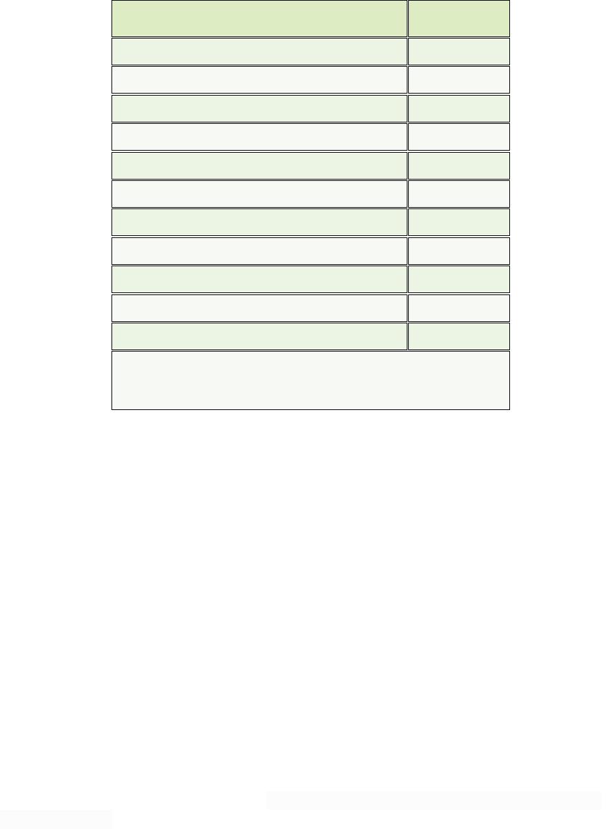
Material
Sensitivity (S) OR
Gauge Factor (GF)
Platinum (Pt 100%)
6.1
Platinum–Iridium (Pt 95%, Ir 5%)
5.1
Platinum–Tungsten (Pt 92%, W 8%)
4.0
Isoelastic (Fe 55.5%, Ni 36% Cr 8%, Mn 0.5%) *
3.6
Constantan / Advance / Copel (Ni 45%, Cu 55%) *
2.1
Nichrome V (Ni 80%, Cr 20%) *
2.1
Karma (Ni 74%, Cr 20%, Al 3%, Fe 3%) *
2.0
Armour D (Fe 70%, Cr 20%, Al 10%) *
2.0
Monel (Ni 67%, Cu 33%) *
1.9
Manganin (Cu 84%, Mn 12%, Ni 4%) *
0.47
Nickel (Ni 100%)
–12.1
* Isoelastic, Constantan, Advance, Copel, Nichrome V, Karma,
Armour D, Monel, and Manganin are all trade names owned by the
respective owners.
Load Cell: A load cell is a type of transducer, specifically a force transducer. They convert a
force such as tension, compression, pressure, or torque into an electrical signal that can be
measured and standardized. As the force applied to the load cell increases, the electrical
signal changes proportionally. The most common types of load cell used are hydraulic,
pneumatic, and strain gauge.
There are several types of strain gauge load cells:
Bending beam: uses strain gauges to monitor the stress in the sensing element when spring
element is subjected to bending forces.
Pancake: low–profile load cells often used in vessel weighing; can be tension or
compression.
Single point shear beam load cell: spring element fixed at one end and loaded on the other.
Double–ended shear beam: spring element fixed at both ends and loaded in the center.
Canister load cell: Cylindrical shaped spring element; can be used in both tension and
compression
S-type load cell: S-shaped spring element; can be used in both compression and tension
Wire rope clamps: an assembly attached to a wire rope and measures its tension; commonly
used in crane and hoist applications.
Tension link load cell: is often used in crane and hoist weighing systems. Measures tension
force only.
Load pin: replaces pulleys and sheave [pronounced “shiv” is the rotating, grooved wheel
inside the pulley] typically on cranes.
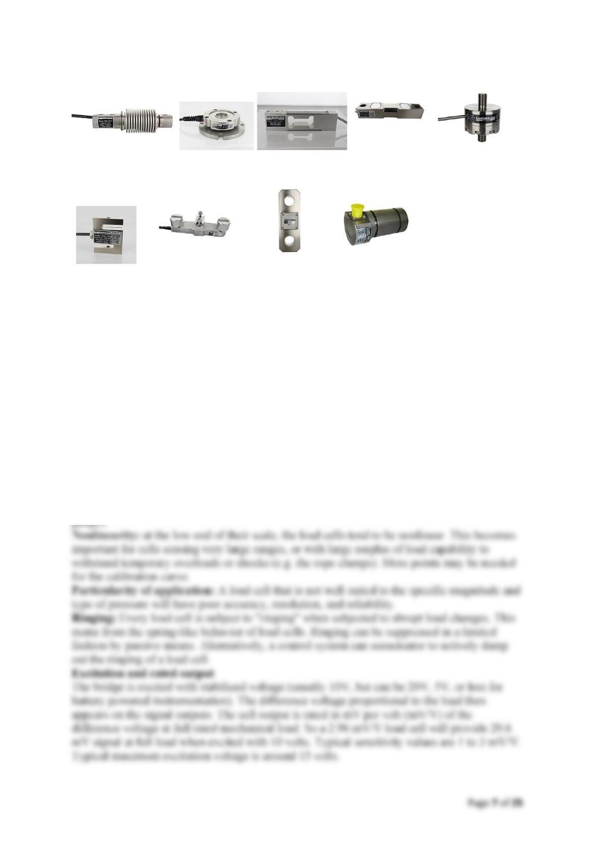
Bending beam Pancake Single point shear beam Double–ended shear beam Canister
S-type Wire rope clamps Tension link Load pin
Common Problems
Mechanical mounting: the cells have to be properly mounted. All the load force has to go
through the part of the load cell where its deformation is sensed. Wrong mounting may result
in the cell reporting forces along undesired axis.
Overload: Within its rating, the load cell deforms elastically and returns to its shape after
being unloaded. If subjected to loads above its maximum rating, the material of the load cell
may go into plastic state; this may result in a signal offset, loss of linearity, difficulty with or
impossibility of calibration, or even mechanical damage to the sensing element.
Wiring issues: the wires to the cell may develop high resistance (e.g. due to corrosion),
parallel current paths can be formed by ingress of moisture leading to signal offset (unless all
wires are affected equally) and accuracy is lost.
Electrical damage: the load cells can be damaged by induced or conducted current.
Lighting hitting the construction, or arc welding performed near the cells, can overstress the
fine resistors of the strain gauges and cause their damage or destruction. For welding nearby,
it is suggested to disconnect the load cell and short all its pins to the ground, nearby the cell
itself. High voltages can break through the insulation between the substrate and the strain