1. Define and discuss Statistical Process Control and why it is important to use.
Statistical process control is the application of statistical analysis methods to identify and control
variation in a process. There are seven major tools of SPC: 1) Histogram/stem-and-leaf plot, 2) Check
sheet, 3) Pareto chart, 4) Cause-and-effect diagram, 5) Defect concentration diagram, 6) Scatter
diagram, 7) Control chart.
Statistical process control can be applied to any process, with the end goal of determining the amount of
variation the process has and the factors that contribute to the variation. All processes naturally have
variability included within them or common cause variability. Processes operating with only common
cause variability are deemed under statistical control; that is, all variation in the process is accounted for
and accepted as inherent in the process. When variability can be assigned an attributable reason for the
variation, then the variation is called assignable cause variation. Some examples would be operator
error, equipment malfunction, or tool/gage failure. If an operation is running with assignable causes of
variability, then the process is out of statistical control.
Processes that are running outside statistical control have the risk of exceeding specification limits if left
unchecked. By using SPC tools to actively monitor a process and implement corrective action when a
process shows assignable cause variation, a process can be kept running within the limits of the natural
capability of the process, thus reducing or eliminating scrap or rework from the process.
2. What is a control chart? How is it used? What are the benefits of using control charts? Describe
three fundamental principles regarding the statistical basis of control charts and why these principles
are important.
A control chart is one of the SPC tools used to determine whether or not a process is running under
control or not. This chart is a process monitoring technique used to quickly detect the occurrence of
assignable cause variation before non-conforming units are manufactured. Control charts can also be
used to measure the capability of a process.
A control chart has three key features; a centerline, an upper control limit, and a lower control limit.
The centerline represents the average value of the characteristic that is correlated to an in-control state.
The upper and lower control limits are chosen such that if the process is under statistical control, nearly
all of the sample points will fall within them. These limits follow the formula of:
𝑈𝐶𝐿 = 𝜇 + 𝐿𝜎
𝐿𝐶𝐿 = 𝜇 − 𝐿𝜎
Where µ represents the average value of the characteristic (centerline), σ represents standard deviation,
and L is the selected distance of the control limit from the centerline. L is generally applied as 3, such
that the control limits will incorporate 100% of the sample means of a normally distributed data set.
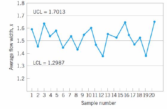
The above is an example of a typical process control chart showing the centerline (1.5), and the UCL and
LCL. In this example, all of the points fall within the control limits suggesting that the process is under
statistical control.
Control charts are subject to type I and type II error. Type I error represents the probability of
concluding the process is out of control when it is not (false alarm). This leads to a root cause
investigation of a phantom assignable cause that doesn’t exist. Type II error represents the probability
that process is in control when it is not. This leads to a condition where a potential assignable cause is
not detected by the control chart therefore failing to detect a shift toward out-of-control.
Control charts can be evaluated for sample size by average run length of the control chart, which is the
average number of points that has to be evaluated before a point indicates an out-of-control condition.
For any Shewhart control chart the ARL = 1/p, where p is the probability that a point exceeds a control
limit. Care must be taken to appropriately use the ARL to evaluate the control chart, as the standard
deviation of the run length can be large and the geometric distribution is skewed, such that the mean of
the distribution (ARL) is not a typical value. However once a process is brought under control, the
geometric distribution may be more normalized and the standard deviation is smaller ARL then is a
useful indicator of the performance of the chart.
Mathematically, a control chart is equivalent to a series of statistical hypothesis tests. The control chart
is a test of the hypothesis that the process is in a state of statistical control, where a point that is plotted
within the control limits would fail to reject the null hypothesis that the process is under statistical
control, and a point falling outside the control limit is rejecting the hypothesis of statistical control.
Control charts are best use to improve a process, since generally most processes do not operate in a
state of statistical control, thus the disciplined use of control charts will assist in identifying assignable
causes of variability. The control chart only provides data, it takes timely implementation of corrective
action to eliminate variation from the process. A control chart also can help prevent unnecessary
process adjustment by distinguishing between variation and noise.

3. Compare and contrast Phase I and Phase II control chart applications, including benefits and
drawbacks of control charts in each phase. Describe which charts are best used in which phase(s) and
provide guidelines for your selection(s).
Phase I control charts use a retrospective analysis using trial control limits to determine whether the
process has been in control over a specific period of time. In Phase I, the control chart is used to help
bring an out-of–control process under statistical control. Control limits are calculated based on the
number of subgroups analyzed and plotted; points out of statistical control are analyzed and assignable
causes are given to each. Corrective actions are implemented on these assignable causes until they are
mitigated or eliminated. The discrepant points are discarded and new control limits are calculated.
Eventually, a “clean” set of data is generated that represents in-control process performance. At that
point phase II can proceed.