15
15.1 Introduction—Modes of Slope Failure
An exposed ground surface that stands at an angle with the horizontal is called an unrestrained
slope. The slope can be natural or man-made. It can fail in various modes. Cruden and Varnes
(1996) classified the slope failures into the following five major categories. They are
1. Fall. This is the detachment of soil and/or rock fragments that fall down a slope
(Figure 15.1). Figure 15.2 shows a fall in which a large amount of soil mass has slid
down a slope.
2. Topple. This is a forward rotation of soil and/or rock mass about an axis below the
center of gravity of mass being displaced (Figure 15.3).
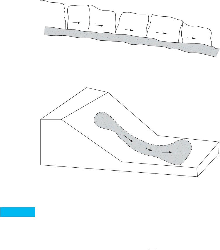
3. Slide. This is the downward movement of a soil mass occurring on a surface of
rupture (Figure 15.4).
4. Spread. This is a form of slide (Figure 15.5) by translation. It occurs by “sudden
movement of water-bearing seams of sands or silts overlain by clays or loaded by
fills” (Cruden and Varnes, 1996).
5. Flow. This is a downward movement of soil mass similar to a viscous fluid
(Figure 15.6).
This chapter primarily relates to the quantitative analysis that fall under the category
of slide.
512
Slope Stability
Figure 15.1
“Fall” type of landslide
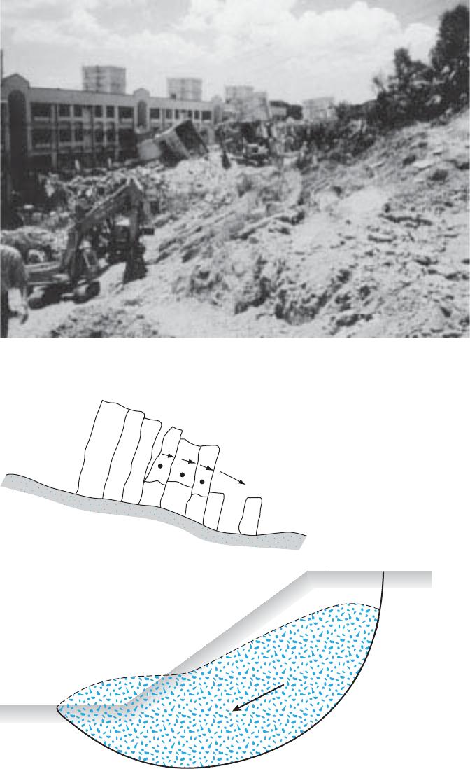
Figure 15.2
Soil and rock “fall” in a slope (Courtesy of E.C. Shin, University of Inchon,
South Korea)
513
Figure 15.3
Slope failure
by “toppling”
Figure 15.4
Slope failure by “sliding”
514
Chapter 15: Slope Stability
15.2 Factor of Safety
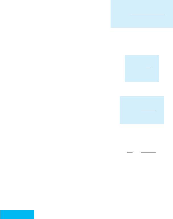
The task of the engineer charged with analyzing slope stability is to determine the factor
of safety. Generally, the factor of safety is defined as
(15.1)
The shear strength of a soil consists of two components, cohesion and friction, and
may be written as
(15.2)
s¿normal stress on the potential failure surface
f¿angle of friction
where c¿cohesion
tfc¿s¿ tan f¿
tdaverage shear stress developed along the potential failure surface
tfaverage shear strength of the soil
where F
sfactor of safety with respect to strength
F
s
tf
td
Figure 15.5
Slope failure by lateral “spreading”
Figure 15.6
Slope failure by “flowing”
15.3 Stability of Infinite Slopes
515
In a similar manner, we can write
(15.3)
where and are, respectively, the cohesion and the angle of friction that develop along
the potential failure surface. Substituting Eqs. (15.2) and (15.3) into Eq. (15.1), we get
(15.4)
Now we can introduce some other aspects of the factor of safety—that is, the fac-
tor of safety with respect to cohesion, and the factor of safety with respect to friction,
They are defined as
(15.5)
and
(15.6)
When we compare Eqs. (15.4) through (15.6), we can see that when becomes
equal to it gives the factor of safety with respect to strength. Or, if
then we can write
(15.7)
When Fsis equal to 1, the slope is in a state of impending failure. Generally, a value
of 1.5 for the factor of safety with respect to strength is acceptable for the design of a stable
slope.
15.3 Stability of Infinite Slopes
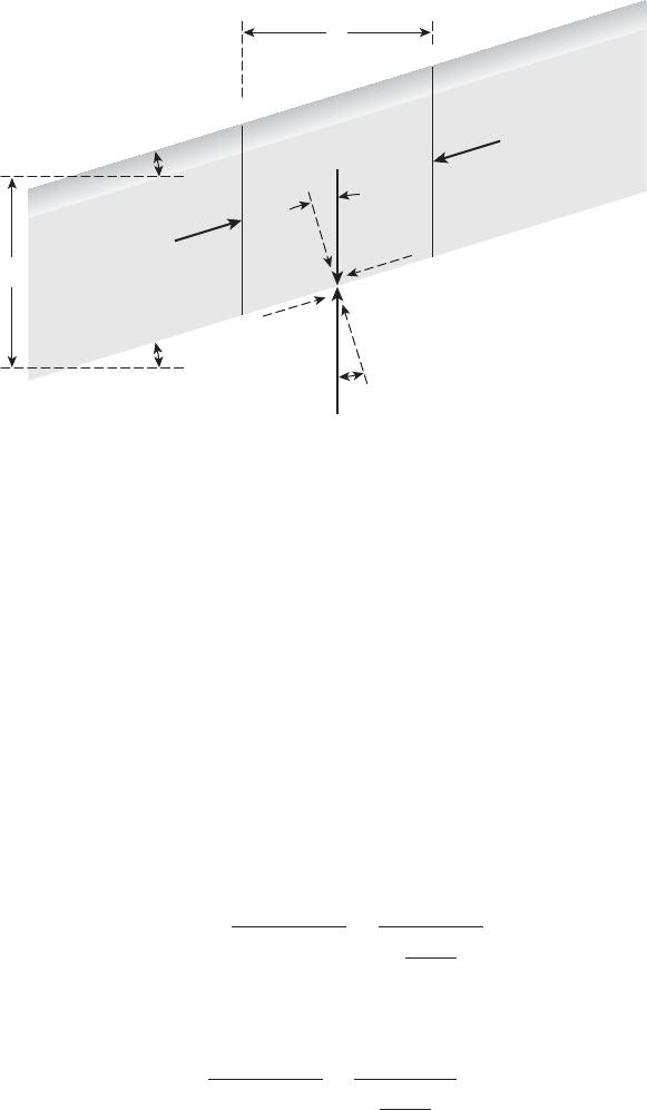
In considering the problem of slope stability, let us start with the case of an infinite slope
as shown in Figure 15.7. The shear strength of the soil may be given by Eq. (15.2):
Assuming that the pore water pressure is zero, we will evaluate the factor of safety
against a possible slope failure along a plane AB located at a depth Hbelow the ground
surface. The slope failure can occur by the movement of soil above the plane AB from
right to left.
tfc¿s¿ tan f¿
F
sF
c¿F
f¿
c¿
cœ
d
tan f¿
tan fœ
d
F
f¿,
F
c¿
F
f¿tan f¿
tan fœ
d
F
c¿c¿
cœ
d
F
f¿.
F
c¿,
F
sc¿s¿ tan f¿
cœ
ds¿ tan fœ
d
fœ
d
cœ
d
tdcd
œs¿ tan fœ
d
516
Chapter 15: Slope Stability
Let us consider a slope element abcd that has a unit length perpendicular to the plane
of the section shown. The forces, F, that act on the faces ab and cd are equal and opposite
and may be ignored. The weight of the soil element is
(15.8)
The weight Wcan be resolved into two components:
1. Force perpendicular to the plane AB NaWcos bgLH cos b.
2. Force parallel to the plane AB TaWsin bgLH sin b. Note that this is the
force that tends to cause the slip along the plane.
Thus, the effective normal stress and the shear stress at the base of the slope element
can be given, respectively, as
(15.9)
and
(15.10)
The reaction to the weight Wis an equal and opposite force R. The normal and tan-
gential components of Rwith respect to the plane AB are
(15.11)N
rR cos bW cos b
tT
a
Area of base gLH sin b
aL
cos bbgH cos b sin b
s¿N
a
Area of base gLH cos b
aL
cos bbgH cos2b
W1Volume of soil element21Unit weight of soil 2gLH
d
a
b
c
F
FTa
Tr
W
R
Na
b
bNr
b
L
A
B
H
b
Figure 15.7
Analysis of infinite slope (without seepage)

15.3 Stability of Infinite Slopes
517
and
(15.12)
For equilibrium, the resistive shear stress that develops at the base of the element is equal
to (Tr)/(Area of base) gHsin bcos b. The resistive shear stress also may be written in
the same form as Eq. (15.3):
The value of the normal stress is given by Eq. (15.9). Substitution of Eq. (15.9) into Eq.
(15.3) yields
(15.13)
Thus,
or
(15.14)
The factor of safety with respect to strength has been defined in Eq. (15.7), from
which we get
Substituting the preceding relationships into Eq. (15.14), we obtain
(15.15)
For granular soils, c0, and the factor of safety, Fs, becomes equal to (tan f)/
(tan b). This indicates that in an infinite slope in sand, the value of Fsis independent of the
height Hand the slope is stable as long as bf.
If a soil possesses cohesion and friction, the depth of the plane along which criti-
cal equilibrium occurs may be determined by substituting Fs1 and HHcr into
Eq. (15.15). Thus,
(15.16)
Hcr c¿
g
1
cos2b1tan btan f¿2
F
sc¿
gH cos2b tan btan f¿
tan b
tan fœ
dtan f¿
F
s
and
cœ
dc¿
F
s
cos2b1tanbtan fœ
d2
cœ
d
gHsin b cos bcos2b tan fœ
d
gH sin b cos bcœ
dgH cos2b tan fœ
d
tdcœ
dgH cos2b tan fœ
d
tdcœ
ds¿ tan fœ
d
T
rR sin bW sin b
518
Chapter 15: Slope Stability
Ta
Tr
W
R
Na
Nr
b
c
d
a
Direction of seepage
B
A
b
H
b
L
Figure 15.8
Infinite slope
with steady-
state seepage
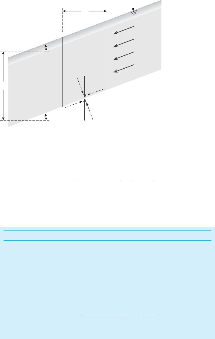
If there is steady state seepage through the soil and the ground water table coincides
with the ground surface, as shown in Figure 15.8, the factor of safety against sliding can
be determined as
(15.17)
where
sat saturated unit weight of soil
sat
weffective unit weight of soil
F
scœ
gsatH cos
2b tan bgœ tan fœ
gsat tan b
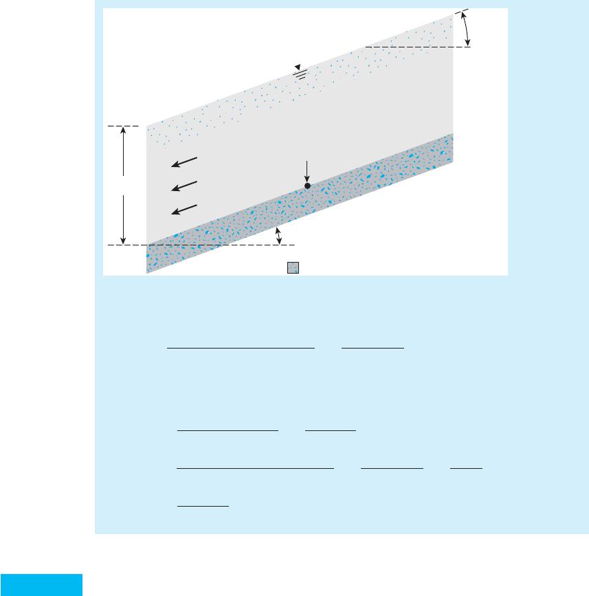
Example 15.1
For the infinite slope with a steady state seepage shown in Figure 15.9, determine:
a. The factor of safety against sliding along the soil-rock interface.
b. The height, H, that will give a factor of safety (Fs) of 2 against sliding along
the soil-rock interface.
Solution
Part a
From Eq. (15.17),
gsat 17.8 kN/m3
F
scœ
gsatH cos
2b tan bgœ tan fœ
gsat tan b
15.4 Finite Slopes— General
519
Figure 15.9
Part b
■
H2.247
20.61 1.62 m
210
117.821H21 cos 15221 tan 15 27.99 tan 20
17.8 tan 15 2.247
H0.61
F
scœ
gsatH cos
2b tan bgœ tan fœ
gsat tan b
F
s10
117.821621cos 15221tan 1527.99 tan 20
17.8 tan 15 0.375 0.61 0.985
gœgsat gw17.8 9.81 7.99 kN/m3
Rock
b 15
H 6 m
b 25
17.8 kN/m3
10 kN/m2
20
gsat
c
f
Seepage
15.4 Finite Slopes— General
When the value of Hcr approaches the height of the slope, the slope generally may be
considered finite. For simplicity, when analyzing the stability of a finite slope in a
homogeneous soil, we need to make an assumption about the general shape of the sur-
face of potential failure. Although considerable evidence suggests that slope failures
usually occur on curved failure surfaces, Culmann (1875) approximated the surface of
potential failure as a plane. The factor of safety, Fs, calculated by using Culmann’s
approximation, gives fairly good results for near-vertical slopes only. After extensive
investigation of slope failures in the 1920s, a Swedish geotechnical commission rec-
ommended that the actual surface of sliding may be approximated to be circularly
cylindrical.
Since that time, most conventional stability analyses of slopes have been made by
assuming that the curve of potential sliding is an arc of a circle. However, in many
circumstances (for example, zoned dams and foundations on weak strata), stability analy-
sis using plane failure of sliding is more appropriate and yields excellent results.
15.5 Analysis of Finite Slopes with Plane
Failure Surfaces (Culmann’s Method)
Culmann’s analysis is based on the assumption that the failure of a slope occurs along a
plane when the average shearing stress tending to cause the slip is more than the shear
strength of the soil. Also, the most critical plane is the one that has a minimum ratio of the
average shearing stress that tends to cause failure to the shear strength of soil.
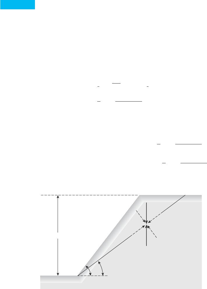
Figure 15.10 shows a slope of height H. The slope rises at an angle bwith the hori-
zontal. AC is a trial failure plane. If we consider a unit length perpendicular to the section
of the slope, we find that the weight of the wedge ABC is equal to
(15.18)
The normal and tangential components of Wwith respect to the plane AC are as
follows.
(15.19)
(15.20)T
atangential component W sin u1
2gH2csin1bu2
sin b sin udsin u
N
anormal component W cos u1
2gH2csin1bu2
sin b sin udcos u
1
2gH2csin1bu2
sin b sin ud
W1
21H21BC21121g21
2H1H cot uH cot b2g
520
Chapter 15: Slope Stability
H
u
b
A
R
Nr
tf cstan f
Unit weight of soil g
Ta
Tr
C
W
B
Na
Figure 15.10
Finite slope
analysis—
Culmann’s
method
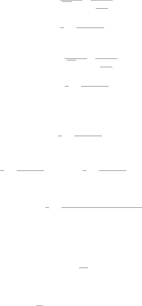
15.5 Analysis of Finite Slopes with Plane Failure Surfaces (Culmann’s Method)
521
The average effective normal stress and the average shear stress on the plane AC are,
respectively,
(15.21)
and
(15.22)
The average resistive shearing stress developed along the plane AC also may be
expressed as
(15.23)
Now, from Eqs. (15.22) and (15.23),
(15.24)
or
(15.25)
The expression in Eq. (15.25) is derived for the trial failure plane AC. In an effort
to determine the critical failure plane, we must use the principle of maxima and minima
(for a given value of ) to find the angle uwhere the developed cohesion would be max-
imum. Thus, the first derivative of cdwith respect to uis set equal to zero, or
(15.26)
Because g,H, and bare constants in Eq. (15.25), we have
(15.27)
0
0u3sin1bu21sin ucos u tan fœ
d240
0cœ
d
0u0
fœ
d
cd1
2gHcsin1bu21sin ucos u tan fœ
d2
sin bd
1
2gHcsin1bu2
sin b sin udsin2ucœ
d1
2gHcsin1bu2
sin b sin udcos u sin u tan fœ
d
cœ
d1
2gHcsin1bu2
sin b sin udcos u sin u tan fœ
d
tdcœ
ds¿ tan fœ
d
1
2gHcsin1bu2
sin b sin udsin2u
tT
a
1AC2112T
a
aH
sin ub
1
2gHcsin1bu2
sin b sin udcos u sin u
s¿N
a
1AC2112N
a
aH
sin ub

522
Chapter 15: Slope Stability
Solving Eq. (15.27) gives the critical value of u,or
(15.28)
Substitution of the value of uucr into Eq. (15.25) yields
(15.29)
The preceding equation also can be written as
(15.30)
where mstability number.
The maximum height of the slope for which critical equilibrium occurs can be
obtained by substituting cand finto Eq. (15.29). Thus,
(15.31)
Hcr 4c¿
gcsin b cos f¿
1cos1bf¿2d
fœ
dcœ
d
cœ
d
gHm1cos1bfœ
d2
4 sin b cos fœ
d
cœ
dgH
4c1cos1bfœ
d2
sin b cos fœ
dd
ucr bfœ
d
2
Example 15.2
A cut is to be made in a soil having g105 lb/ft3,c600 lb/ft2, and f15. The
side of the cut slope will make an angle of 45with the horizontal. What should be the
depth of the cut slope that will have a factor of safety (Fs) of 3?
Solution
Given: f15;c600 lb/ft2. If Fs3, then and should both be equal to 3.
or
Similarly,
tan fœ
dtan f¿
Ffœ
tan f¿
Fs
tan 15
3
Ffœtan f¿
tan fœ
d
cœ
dc¿
Fcœ
c¿
Fs
600
3200 lb/ft2
Fc¿c¿
cœ
d
Ffœ
Fcœ

15.6 Analysis of Finite Slopes with Circular Failure Surfaces— General
523
15.6 Analysis of Finite Slopes with
Circular Failure Surfaces— General
Modes of Failure
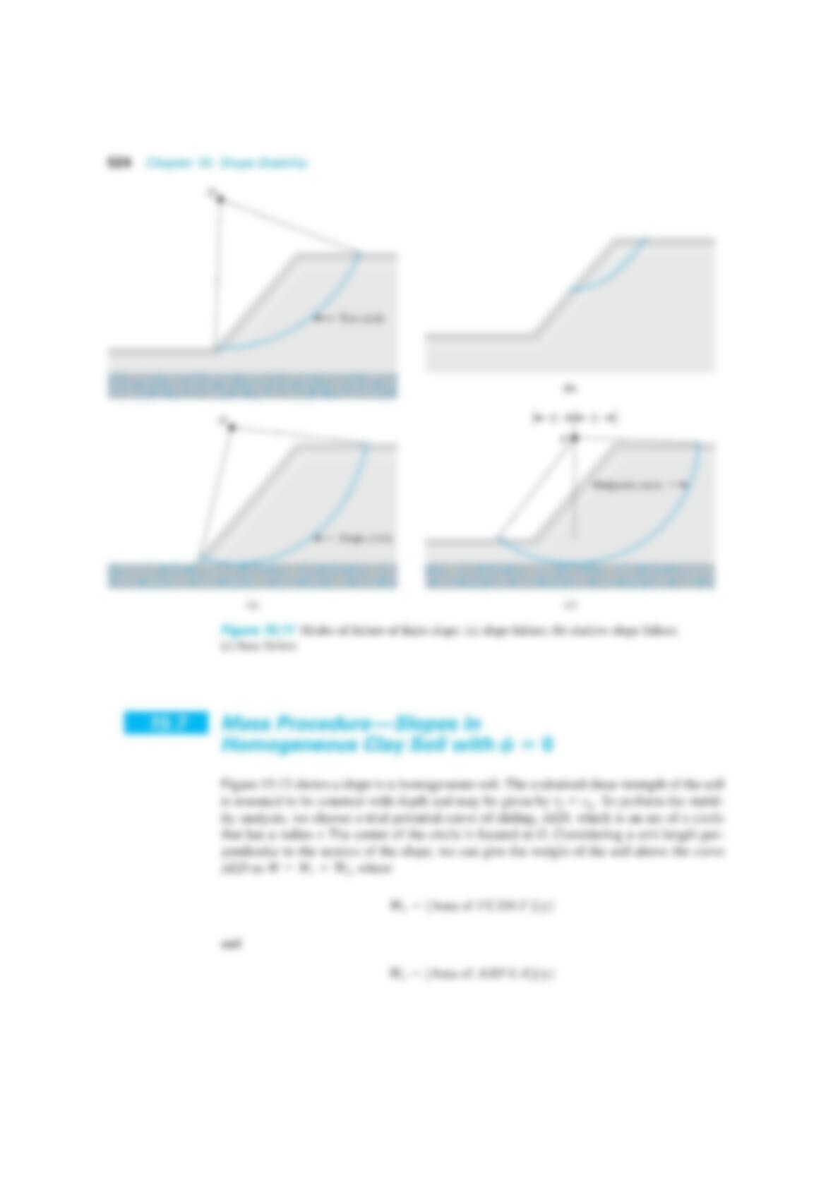
In general, finite slope failure occurs in one of the following modes (Figure 15.11):
1. When the failure occurs in such a way that the surface of sliding intersects the slope
at or above its toe, it is called a slope failure (Figure 15.11a). The failure circle is
referred to as a toe circle if it passes through the toe of the slope and as a slope
circle if it passes above the toe of the slope. Under certain circumstances, a shallow
or
Substituting the preceding values of and in Eq. (15.29)
■23.05 ft
4200
105 csin 45 #cos 5.1
1cos145 5.12d
H4cœ
d
gcsin b#cos fœ
d
1cos1bfœ
d2d
fœ
d
cœ
d
fœ
dtan1ctan 15
3d5.1°