Sunil Jha, Department of Mechanical Engineering, I.I.T. Delhi
CAM and AUTOMATION
MCL 431
CAM AND AUTOMATION
1
Dr. Sunil Jha
suniljha@mech.iitd.ac.in
Office: Block III/156
Hydraulic Circuit Analysis
Sunil Jha, Department of Mechanical Engineering, I.I.T. Delhi
CAM and AUTOMATION
Hydraulic Circuit Analysis
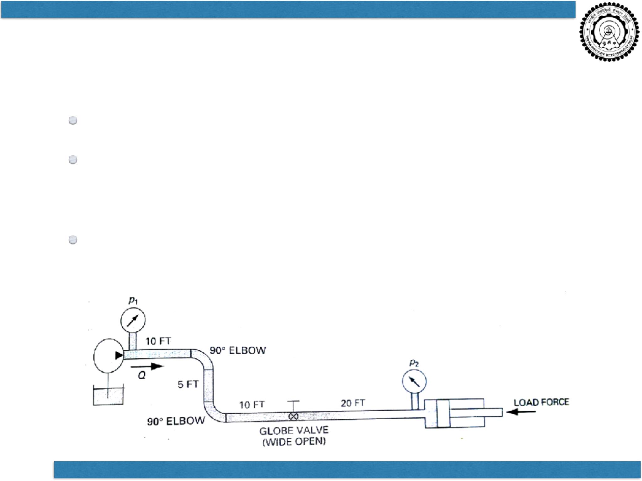
Energy Losses in Fluid Power Systems.
Bernoulli‘s equation & Continuity equation
•Used to perform analysis of Fluid Power System
Calculating Pressure drops, flow rates, HP
losses for all components.

Sunil Jha, Department of Mechanical Engineering, I.I.T. Delhi
CAM and AUTOMATION
Laminar / Turbulent
Reynolds number
< 2000 : LAMINAR
> 4000 : TURBULENT
CRITICAL ZONE
Greater losses in Turbulent flow
Fluid power system designed to operate
in LAMINAR flow region

Sunil Jha, Department of Mechanical Engineering, I.I.T. Delhi
CAM and AUTOMATION
Friction Losses
Friction – Main cause of losses
Loss in Pressure head
Head Loss
•Losses in Pipes
•Losses in Fittings
Head loss in Pipes – Darcy-Weisbach’s Equation
Friction losses are a complex function of the
system geometry, the fluid properties and
the flow rate in the system
Sunil Jha, Department of Mechanical Engineering, I.I.T. Delhi
CAM and AUTOMATION
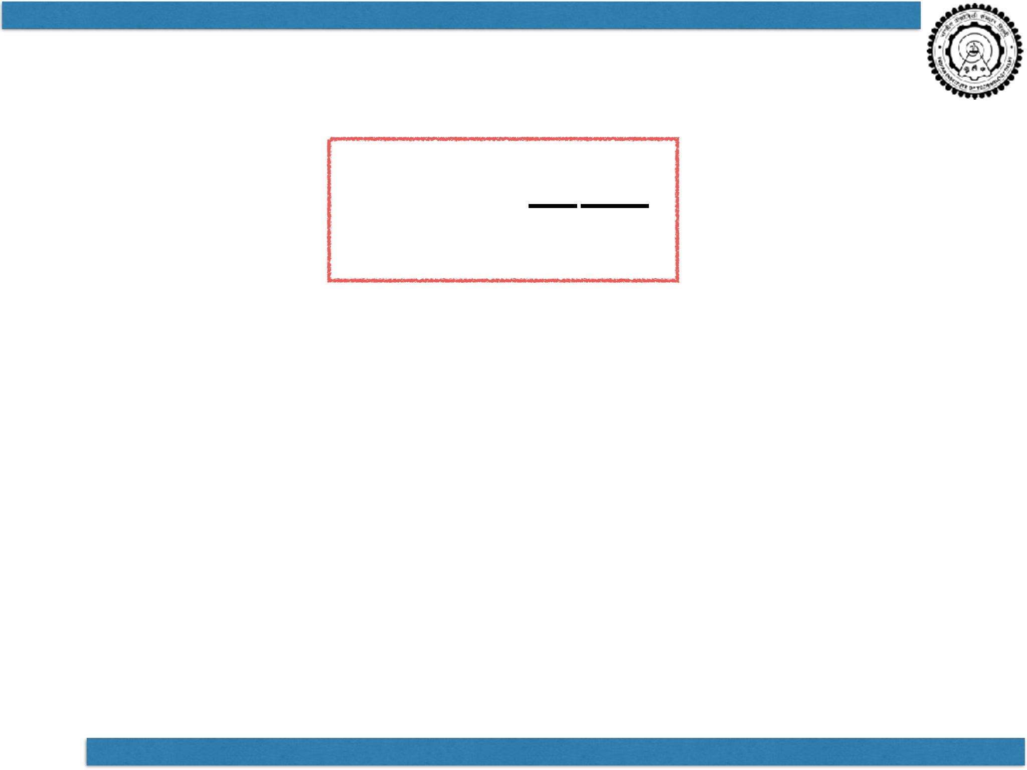
Darcy-Weisbach Equation
f = Friction factor
L = Length of pipe
D = Pipe inside diameter
V = Average fluid velocity
g = Acceleration due to gravity
HL
=
f
L
D
V2
2g
Difference lies in evaluation of friction factor
Used for Laminar as well as Turbulent flow
Sunil Jha, Department of Mechanical Engineering, I.I.T. Delhi
CAM and AUTOMATION
Friction Losses in Laminar Flow
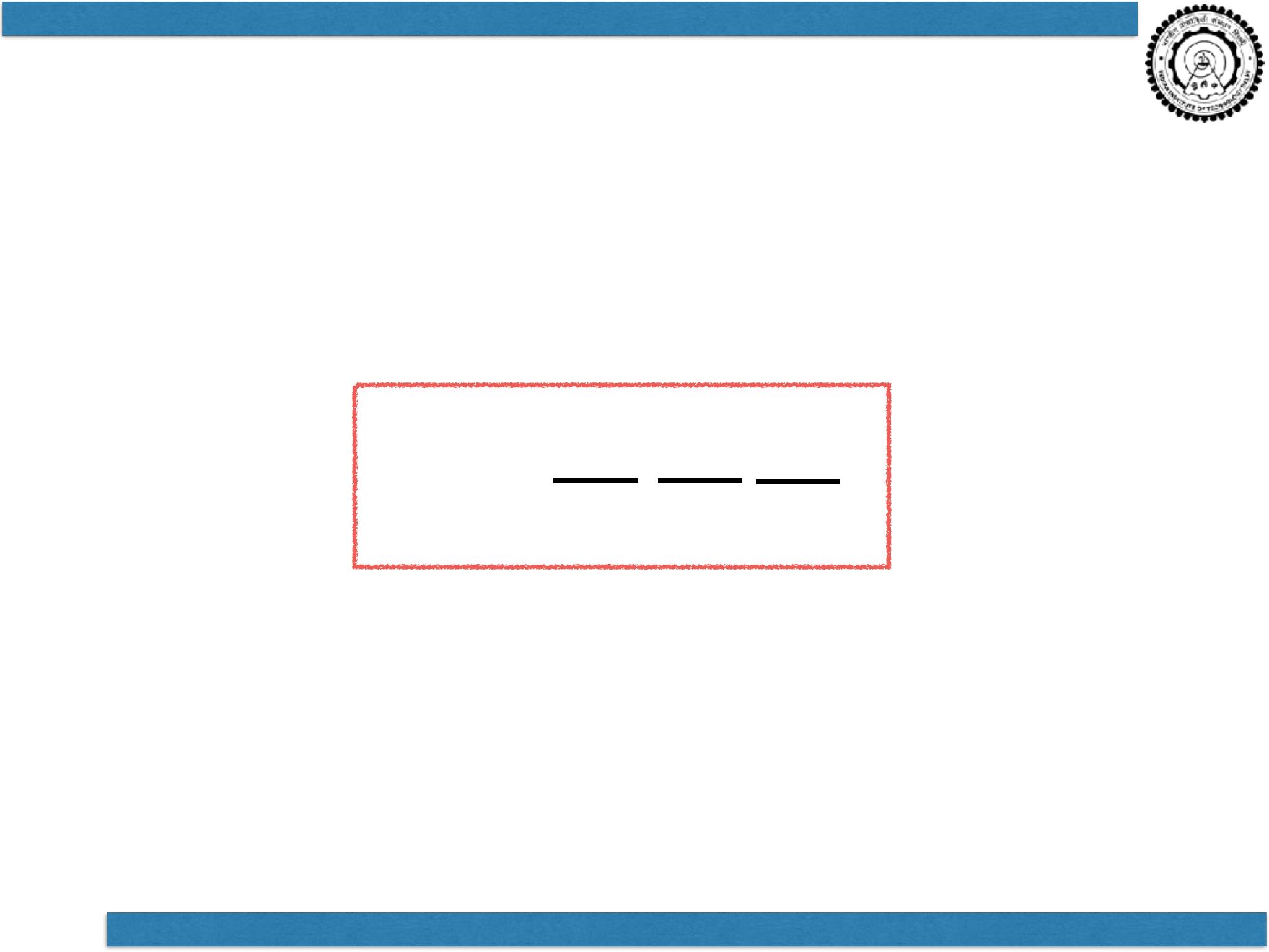
Hagen Poiseuille Equation
Friction Factor, f = 64 / (Reynolds No.)
HL
=
64
L
D
V2
2g
Re

CAM and AUTOMATION
Friction Losses in Turbulent Flow
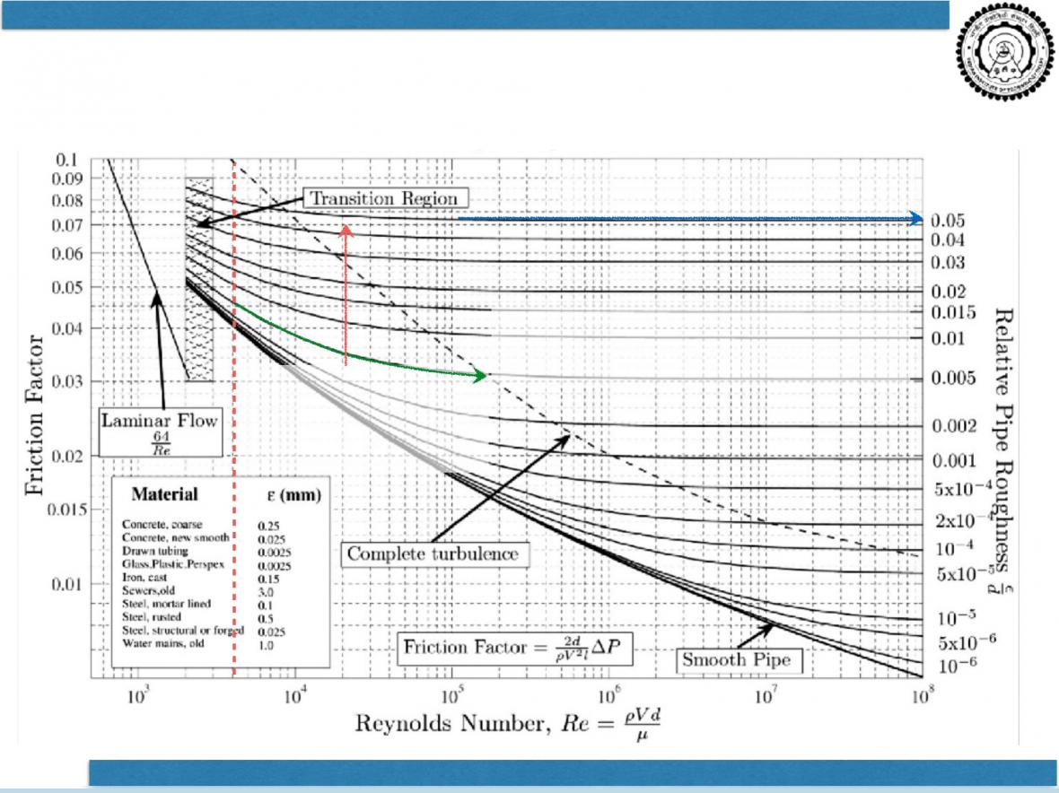
Relative roughness = ε/D
ε = absolute roughness
Drawn tubing = 1.524
Commercial steel = 45.72