future internet
Review
Software Defined Networking Flow Table
Management of OpenFlow Switches Performance
and Security Challenges: A Survey
Babangida Isyaku 1,2,* , Mohd Soperi Mohd Zahid 3, Maznah Bte Kamat 1,
Kamalrulnizam Abu Bakar 1and Fuad A. Ghaleb 1
1
Department of Computer Science, Faculty of Engineering, Universiti Teknologi Malaysia, Johor Bahru 81310,
Malaysia; kmaznah@utm.my (M.B.K.); knizam@utm.my (K.A.B.); aafuad@utm.my (F.A.G.)
2Department of Mathematics and Computer Science, Sule Lamido University,
Kafin Hausa P.M.B 048, Jigawa State, Nigeria
3Department of Computer and Information Science, Universiti Teknologi PETRONAS, Seri,
Iskandar Perak 32610, Malaysia; msoperi.mzahid@utp.edu.my
*Correspondence: isyaku@graduate.utm.my; Tel.: +60-1161-110-962
Received: 11 August 2020; Accepted: 26 August 2020; Published: 31 August 2020
Abstract:
Software defined networking (SDN) is an emerging network paradigm that decouples
the control plane from the data plane. The data plane is composed of forwarding elements called
switches and the control plane is composed of controllers. SDN is gaining popularity from industry
and academics due to its advantages such as centralized, flexible, and programmable network
management. The increasing number of traffics due to the proliferation of the Internet of Thing (IoT)
devices may result in two problems: (1) increased processing load of the controller, and (2) insufficient
space in the switches’ flow table to accommodate the flow entries. These problems may cause
undesired network behavior and unstable network performance, especially in large-scale networks.
Many solutions have been proposed to improve the management of the flow table, reducing controller
processing load, and mitigating security threats and vulnerabilities on the controllers and switches.
This paper provides comprehensive surveys of existing schemes to ensure SDN meets the quality of
service (QoS) demands of various applications and cloud services. Finally, potential future research
directions are identified and discussed such as management of flow table using machine learning.
Keywords: SDN; OpenFlow; rule management; update operation; security threat
1. Introduction
The number of internet-connected or Internet of Things (IoT) devices, and traffic flow volume in
the internet has significantly increased and continues to grow. According to Pierre et al. [
1
], the number
of active internet-connected devices was 26.66 billion in 2019. The annual global network traffic
flow as of 2018 amounted to 19.01 exabytes per month and is expected to reach 77.5 exabytes per
month by 2022 worldwide [
1
]. The data flows are coming mostly from IoT devices and stored in
data centers, which provide various and increasing kinds of cloud services to users. Managing the
internet and data centers to meet the expanding demands of emerging applications such as real-time
has become a big challenge in traditional networking. The integration of control and forwarding
logic in routers and switches in traditional networking introduces some limitations and inflexibility in
managing and monitoring the networks to configure the optimum quality of service (QoS) provisioning.
The configuration of policies (e.g., firewall and routing policies) required network operators to adhere
to the vendor-specific interfaces of routers and switches to configure the device [
1
]. Adjustments to
the network have to be made by the network administrator more conveniently and promptly to cope
Future Internet 2020,12, 147; doi:10.3390/fi12090147 www.mdpi.com/journal/futureinternet
Future Internet 2020,12, 147 2 of 30
with dynamic network behaviors such as fault management and load changes [
2
]. Despite the wide
adoption of internet protocol (IP) based networks, automatic reconfiguration and response to network
changes are difficult in the current conventional networks, according to Kreutz et al. [2].
SDN decouples the control plane (networking logic) from the data plane (forwarding logic) [
3
].
The control plane consists of controllers acting as a network operating system and the data plane
consists of switches, which mainly forward packets to the next hop. The controller is responsible for
maintaining the global network state in real-time. The separation between control and data planes
is achieved using a standard communication interface such as OpenFlow [
4
]. OpenFlow switches
have Flow Table, which is commonly implemented with Ternary Content Addressable Memory
(TCAM) technology. Typically, a flowtable is populated with rules or policies such as quality of
service (QoS), access control lists (ACLs), and IP route tables for fast-forwarding. However, TCAM is
power-hungry, expensive, and available in limited space or capacity that can only accommodate from
750 to 20,000 flow entries [
5
,
6
]. Thus, the flow table is relatively small compared to the number of
required rules. The centralized architecture of SDN and space limitations of the flow table introduce
some performance and security issues. Attackers may overwhelm the flow table with multiple denial
of service (DoS) attacks and manipulate the controller to refuse writing legitimate flow entries [
7
].
Mitigating the DoS attacks requires the installation of a large number of access control list (ACL)
distributed rules while TCAM is available in only limited capacity or space.
SDN controller populates or updates the flow table reactively or proactively upon occurrence of
some events. In a reactive approach, the controller does not populate the flow table with any rules when
network operation begins. Whenever packets arrive at switches during network operation, rules will
be installed into the flow table by the controller. For the proactive approach, the controller will install
flow entries in the flow table in advance, when network operation begins. The selection of rules is
imperative in maximizing network performance especially in large-scale networks such as data centers.
When packets arrive at a switch during network operation, the flow of arriving packet is matched
against flow entries in the flow table. If matching is not found, the switch will contact the controller
to update the flow table with entries that allow the packet to reach its destination. This involves
communication overhead between controller and switch as well as delay until the packet can be
forwarded to the next hop. The proactive approach was introduced to reduce the communication
overhead involved between switches and controllers.
Another SDN performance issue is regarding the flow table update operation made upon the
occurrence of events such as topology changes [
5
], network reconfiguration [
6
], and the creation of
re-routing rules [
7
]. The routing update operation must be completed within 25 milliseconds (ms) to
meet stringent QoS requirements of real-time applications [
8
]. Similarly, failure recovery has a strict
recovery delay requirement to adhere to the carrier-grade quality [
8
]. Fast rules rerouting depends
on switch rule updating time and controller response time to generate rules. A common challenge
experienced by the SDN controller is to update the switches consistently and promptly. The longer time
the update operation takes, the more probability for the network to have unstable behaviors such as
extra packet processing delay, forwarding loop, and routing errors [
7
]. Thus, the centralized controller,
flow table limitation of commercial switches, and flow table update operation should be dealt with
efficiently to avoid critical performance bottleneck in the deployed production network environment
of OpenFlow-SDN [
5
]. These three issues of SDN have gained great attention from researchers in
recent years [
7
–
11
]. DevoFlow [
9
], DIFANE [
12
], and Kotani [
13
] proposed some schemes to reduce
the processing load of the controller. SDN-Guard [
14
–
16
] have proposed some methods to mitigate
security attacks arisen due to the centralized nature of the controller in SDN. Some solutions were
proposed to reduce higher flowtable update operations [
7
,
17
,
18
]. Other solutions focus on improving
the efficiency of a limited flowtable [19–21].
This paper provides a comprehensive survey on the efforts that have been done on optimizing
the processing load of the controller, mitigating malicious attacks, flow table update operation,
and improving the efficiency of flow table management to ensure stable performance of SDN.
Future Internet 2020,12, 147 3 of 30
Potential future research directions are also identified and discussed, such as the use of machine
learning and other artificial intelligence techniques. The paper road map is organized as follows:
Section 2presents an overview of OpenFlow as a promising standard to achieve the benefit of
SDN. Section 3explains SDN performance challenges. Section 4presents and details the existing
state-of-the-art proposed solutions to manage flow table memory. Section 5discusses and highlights
the research challenges and suggests future research direction. Section 6rounds up the paper and
presents concluding remarks.
2. Overview of SDN Architecture
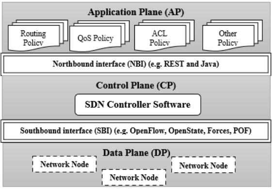
SDN consists of three planes: application plane (AP), control plane (CP), and data plane
(DP), as depicted in Figure 1. Application planes consist of network applications such as network
virtualization, firewalls, intrusion detection system (IDS), and mobility management that leverage the
exposed northbound (NB) application interface to interact with the control plane. The NB interface
provides a stable, consistent way for network administrators and application developers to efficiently
use SDN services to implement important network management at the control plane. The CP is
the most essential part of the SDN structure, it provides fine-grained control over the networking
element at the DP and offers many network services, which include routing computation, monitoring,
load balancing. The CP translates these services from application-level into a clear set of instructions
and requests in form of flow entries and installs them in the corresponding switch devices. Single CP
can be configured for the entire network, but for scalability reasons, it can be extended to distributed
or multiple controllers. As for the DP, they are used as a simpler forwarding element with no software
capable of making an instant decision. Therefore, network intelligence is withdrawn and shifted to a
centrally logical controller. For any control decision, the switch must consult the controller for further
action. This paper focus on the control plane and data plane.
Future Internet 2020, 12, x FOR PEER REVIEW 3 of 30
improving the efficiency of flow table management to ensure stable performance of SDN. Potential
future research directions are also identified and discussed, such as the use of machine learning and
other artificial intelligence techniques. The paper road map is organized as follows: Section 2 presents
an overview of OpenFlow as a promising standard to achieve the benefit of SDN. Section 3 explains
SDN performance challenges. Section 4 presents and details the existing state-of-the-art proposed
solutions to manage flow table memory. Section 5 discusses and highlights the research challenges
and suggests future research direction. Section 6 rounds up the paper and presents concluding
remarks.
2. Overview of SDN Architecture
SDN consists of three planes: application plane (AP), control plane (CP), and data plane (DP), as
depicted in Figure 1. Application planes consist of network applications such as network
virtualization, firewalls, intrusion detection system (IDS), and mobility management that leverage
the exposed northbound (NB) application interface to interact with the control plane. The NB
interface provides a stable, consistent way for network administrators and application developers to
efficiently use SDN services to implement important network management at the control plane. The
CP is the most essential part of the SDN structure, it provides fine-grained control over the
networking element at the DP and offers many network services, which include routing computation,
monitoring, load balancing. The CP translates these services from application-level into a clear set of
instructions and requests in form of flow entries and installs them in the corresponding switch
devices. Single CP can be configured for the entire network, but for scalability reasons, it can be
extended to distributed or multiple controllers. As for the DP, they are used as a simpler forwarding
element with no software capable of making an instant decision. Therefore, network intelligence is
withdrawn and shifted to a centrally logical controller. For any control decision, the switch must
consult the controller for further action. This paper focus on the control plane and data plane.
Figure 1. Software defined networking architecture.
2.1. SDN Southbound Interface
OpenFlow is so far the most popular standard for SDN southbound (SB) interface. Earlier
implementations of SB interface were forwarding and control elements (ForCES) and protocol-
oblivious forwarding (POF) [2]. ForCES uses logical function blocks (LFB) in the data forwarding
elements to provide networking functionalities such as IP routing [3]. However, these standards rely
essentially on modifying forwarding devices to support flow tables [2], in a way that can be
dynamically configured by remote entities through operations such as, adding, removing, or
updating flow rules in the flow table. Therefore, a recent initiative such as OpenFlow emerges, which
does not require modifications of the switches to support flowtable. This attracts not only the research
Figure 1. Software defined networking architecture.
2.1. SDN Southbound Interface
OpenFlow is so far the most popular standard for SDN southbound (SB) interface.
Earlier implementations of SB interface were forwarding and control elements (ForCES) and
protocol-oblivious forwarding (POF) [
2
]. ForCES uses logical function blocks (LFB) in the data
forwarding elements to provide networking functionalities such as IP routing [
3
]. However,
these standards rely essentially on modifying forwarding devices to support flow tables [2], in a way
that can be dynamically configured by remote entities through operations such as, adding, removing,
or updating flow rules in the flow table. Therefore, a recent initiative such as OpenFlow emerges,
Future Internet 2020,12, 147 4 of 30
which does not require modifications of the switches to support flowtable. This attracts not only the
research community but also the networking industry [
2
]. OpenFlow became the most popular and
powerful implementation of the SB interface [
22
], standardized by Open Network Foundation [
23
]
to control the behavior of the SDN devices. [
24
] developed OpenState as a superset extension of
Openflow aimed at offloading some of the control logic to switches thereby shifting the pragmatic
approach from stateless to stateful operation. This means the OpenFlow switches can also be directly
programmable, thus they can handle forwarding rules locally without the need to completely depend
on the remote controller. OpenState is yet to be implemented as the future extended version of
OpenFlow [
25
]. In OpenState, the legacy flow table in OpenFlow is preceded by a state table to
processed flow states, by using flow-states and global states. A programmer can define flow entries
that apply to different scenarios, using state transition, a programmer can control the evolvement of
different scenarios. This survey focuses on OpenFlow as the standard southbound interface between
switch to SDN Controller.
2.2. Flow Table of SDN Switches
In SDN, forwarding entities are referred to as OpenFlow switches and all forwarding decisions
are flow-based instead of destination-based as used in the legacy traditional network. An OpenFlow
switch contains a flow table with a logical data structure where packets are processed based on a list of
prioritizing entries. A flow table can store a set of flow entries made of 15 field tuples in OpenFlow
1.10: some of the fields are optional but matching fields, action, statistical counter, priority, and timeout
mechanism are commonly used. Matching fields are used to match packet meta information such as
(medium access control (MAC) source and destination address, ethernet type, internet protocol (IP)
source and destination address). These fields can be specified as either exact-match or wildcard-match
entries. The former represents an individual flow, while the latter represent multiples flows using any
value inform of an asterisk (*). Incoming packets will be looked up in the flowtable, if the packet matches
either exact-match or wildcard flow, the corresponding action will be taken. The statistical count will
be incremented for all successful matches of flow entry with the arriving packet. Wildcard matching
entries are assigned with priorities, if multiple packets match multiple wildcards flow the higher
priority is the final match. Exact match is usually assigned a higher priority than wildcard flows.
If the packet could not match any flow, it will be forwarded to the controller or drop the packet.
Other actions may be forward to specific switch port number. The flow lookup is compulsory for every
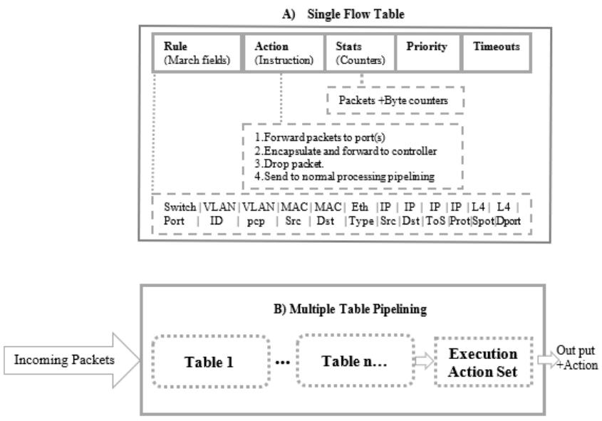
incoming packet. This could be done using a single flowtable or multiple flowtable pipelining up to
255 tables [26] as illustrated in Figure 2:
For efficiency and flexibility reasons, OpenFlow 1.3 [
26
,
27
] supports multiple flow table pipelining
processing where a packet may be processed by more than one flow table. Both the single and
pipelining tables have the four components (matching field, action, statistic, priority, and timeout).
In contrast to the single table, the matching process starts at the first flow table in the pipelining tables
and may continue to the next table until the match flow entry is found. The process of checking entry
is performed sequentially, and action is normally executed at the end of the last table in the pipelining.
If there is no match, the switch may either drop the packet or trigger a packet-in message to the
controller for flow setup request depending on the configuration of the table-miss entry. In the event of
a packet forwarded to the controller for flow setup request, the centralized controller computes new
flow entry and sends a packet-out event to instruct the switch to install the corresponding entry in its
flowtable. Frequent flow setup requests will be sent to the controller on a large scale with the presence
of massive flow arrivals. According to [
27
], there can be up to 200,000 flows arrival/sec for a data
center with a 4 k server. Another previous study report on average flow size shown to have around
20 packets per flow with flow inter-arrival time of less than 30 ms [
28
]. These demands are very high;
however, the memory capacity to store forwarding entries is small. Typical OpenFlow switch flow
tables stored rules in a special type of high-speed memory called ternary content addressable memory
(TCAM), which provides constant flow entry lookup within a single clock cycle O (1). Despite the
Future Internet 2020,12, 147 5 of 30
high-speed lookup, TCAM’s memory is constrained with a few thousand entries [
26
]. Increasing the
TCAM size introduces another concern such as cost and will require high-power consumption.
Future Internet 2020, 12, x FOR PEER REVIEW 5 of 30
[26]. Increasing the TCAM size introduces another concern such as cost and will require high-power
consumption.
Figure 2. Single vs. multiple flow table. (A) Single Flow Table and (B) Multiple Flow Table
respectively.
Lately, software switches built on commodity servers, which are part of the same switch
hardware, are becoming popular [29]. This type of switch can offer a large flow table capacity with a
high packet processing rate of 40 Gbps on a quad-core machine [29]. However, such switches are
constrained in the lookup rate compared to commodity switches [30]. The software switch is designed
based on the general-purpose central processing unit (CPU). In contrast, commodity switch is based
on application-specific integrated circuit (ASIC), which is purposely designed for high-speed lookup
[31]. In addition, software switches stored forwarding rules in the conventional random-access
memory (RAM), which has a relatively lower cost with high storage capacity. OpenFlow switches
store forwarding rules in TCAM, which is designed for matching flexibility and high lookup
performance. Moreover, as explained by [32], installing forwarding rules in software switch instead
of ASIC reduces the OpenFlow switch performance from 940 to 14 Mpbs. To further speedup
switching operation in software switches, it is possible to store a flow table in CPU caches. However,
these caches inherit similar shortcomings of storage limitation, which was introduced in ASIC [32].
Consequently, the shortage introduces a lot of problems, which include but is not limited to extra
packet processing delay, update operation, and signaling overhead. Therefore, the switch flowtable
limitation and frequent flow setup request to controller present great concern, which further needs
to be investigated, especially in a large scales network environment such as data center and IoT.
Section 4 extensively surveys the existing solutions proposed in the literature to cope with the
limitations of the switch flow table memory.
2.3. Installation of Flow Table Entries
Normally, flow entries are installed in the switch flow table in two modes: reactive and proactive
approaches. Similarly, occurrences of some events such as link failure or change in ACL rules may
Figure 2.
Single vs. multiple flow table. (
A
) Single Flow Table and (
B
) Multiple Flow Table respectively.
Lately, software switches built on commodity servers, which are part of the same switch hardware,
are becoming popular [
29
]. This type of switch can offer a large flow table capacity with a high packet
processing rate of 40 Gbps on a quad-core machine [
29
]. However, such switches are constrained
in the lookup rate compared to commodity switches [
30
]. The software switch is designed based
on the general-purpose central processing unit (CPU). In contrast, commodity switch is based on
application-specific integrated circuit (ASIC), which is purposely designed for high-speed lookup [
31
].
In addition, software switches stored forwarding rules in the conventional random-access memory
(RAM), which has a relatively lower cost with high storage capacity. OpenFlow switches store
forwarding rules in TCAM, which is designed for matching flexibility and high lookup performance.
Moreover, as explained by [
32
], installing forwarding rules in software switch instead of ASIC reduces
the OpenFlow switch performance from 940 to 14 Mpbs. To further speedup switching operation
in software switches, it is possible to store a flow table in CPU caches. However, these caches
inherit similar shortcomings of storage limitation, which was introduced in ASIC [
32
]. Consequently,
the shortage introduces a lot of problems, which include but is not limited to extra packet processing
delay, update operation, and signaling overhead. Therefore, the switch flowtable limitation and
frequent flow setup request to controller present great concern, which further needs to be investigated,
especially in a large scales network environment such as data center and IoT. Section 4extensively
surveys the existing solutions proposed in the literature to cope with the limitations of the switch flow
table memory.
2.3. Installation of Flow Table Entries
Normally, flow entries are installed in the switch flow table in two modes: reactive and proactive
approaches. Similarly, occurrences of some events such as link failure or change in ACL rules may
cause the flow table to be updated. Such a situation may require two operations, the old flow entries
Future Internet 2020,12, 147 6 of 30
need to be deleted and the new entry for the alternative flow or ACL rules respectively need to be
installed. In this situation, flow table update operation is necessary. Section 3.2 presents flow table
update operation, while the following sections detail the two approaches and performance issues
associated with each approach were also discussed.
2.3.1. Reactive Flow Table Allocation
Initially, during the network booting time, switch flowtable is empty. Features negotiation
between switch and controller will immediately commence for the controller to discover all the
switches connected. There are two situations where the flowtable will be populated. The first situation
is when the first packet of flows arrives in the switch flowtable. This will cause table-miss because of
the unavailability of the entry. To handle the table-miss, switch performs reactive process through
a packet-in event and sends it to the controller for further decision. The controller computes the
correspondent entry of the flow and updates the switch flowtable of the affected switch. The second
situation is re-installing of flow entries due to flow expiration or flow modification event. Generally,
setting new flow requires 2 or n messages for many flows between the switch to the controller, where n
represents the number of data flows. Packets transmission commence after the rules have been installed.
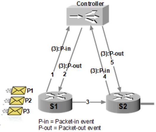
A subsequent packet of the same flow will be processed without consulting the controller. Figure 3
illustrates reactive packet processing. Assume 3 different packets belonging to different flows arrived
at switch S
1
at different time intervals. Packet p
1
arrives at time t
1
, packet p
2
arrives at time t
2
slightly
after t
1,
and packet p
3
arrives at time t
3
slightly after t
3
. The switch performs 3 lookups in its flowtable
after the arrival of packet p
3
. Switch S
1
buffers the 3 packets and generates 3 number of a packet-in
event to request the corresponding flows from the controller as indicated by arrow 1. Upon receiving
each packet-in, the controller computes the flow entries and send a packet-out message back to switch
S
1
instructing the switch to install corresponding entries as shown by arrow 2. Finally, packets are
enqueued and transmitted at full line rate as shown by message 3.
Future Internet 2020, 12, x FOR PEER REVIEW 6 of 30
cause the flow table to be updated. Such a situation may require two operations, the old flow entries
need to be deleted and the new entry for the alternative flow or ACL rules respectively need to be
installed. In this situation, flow table update operation is necessary. Section 3.2 presents flow table
update operation, while the following sections detail the two approaches and performance issues
associated with each approach were also discussed.
2.3.1. Reactive Flow Table Allocation
Initially, during the network booting time, switch flowtable is empty. Features negotiation
between switch and controller will immediately commence for the controller to discover all the
switches connected. There are two situations where the flowtable will be populated. The first
situation is when the first packet of flows arrives in the switch flowtable. This will cause table-miss
because of the unavailability of the entry. To handle the table-miss, switch performs reactive process
through a packet-in event and sends it to the controller for further decision. The controller computes
the correspondent entry of the flow and updates the switch flowtable of the affected switch. The
second situation is re-installing of flow entries due to flow expiration or flow modification event.
Generally, setting new flow requires 2 or n messages for many flows between the switch to the
controller, where n represents the number of data flows. Packets transmission commence after the
rules have been installed. A subsequent packet of the same flow will be processed without consulting
the controller. Figure 3 illustrates reactive packet processing. Assume 3 different packets belonging
to different flows arrived at switch S1 at different time intervals. Packet p1 arrives at time t1, packet p2
arrives at time t2 slightly after t1, and packet p3 arrives at time t3 slightly after t3. The switch performs
3 lookups in its flowtable after the arrival of packet p3. Switch S1 buffers the 3 packets and generates
3 number of a packet-in event to request the corresponding flows from the controller as indicated by
arrow 1. Upon receiving each packet-in, the controller computes the flow entries and send a packet-
out message back to switch S1 instructing the switch to install corresponding entries as shown by
arrow 2. Finally, packets are enqueued and transmitted at full line rate as shown by message 3.
Figure 3. Example of reactive entry installation.
Intuitively, to adjust with the current network state, n number of OpenFlow messages are
exchanged between the two switches to the controller to get flow installed. This can easily decline the
performance of the overall network and degrade the quality of service. Prior study in Liu et al. [28]
reveal that initiating flow setup request for every new incoming flow together with the TCAM update
operation increases the packet processing delay. For instance, upon occurrences of the link failure
event, the controller is expected to reroute all affected flows within 25 milliseconds. The strict delay
Figure 3. Example of reactive entry installation.
Intuitively, to adjust with the current network state, nnumber of OpenFlow messages are
exchanged between the two switches to the controller to get flow installed. This can easily decline the
performance of the overall network and degrade the quality of service. Prior study in Liu et al. [
28
]
reveal that initiating flow setup request for every new incoming flow together with the TCAM update
operation increases the packet processing delay. For instance, upon occurrences of the link failure
event, the controller is expected to reroute all affected flows within 25 milliseconds. The strict delay
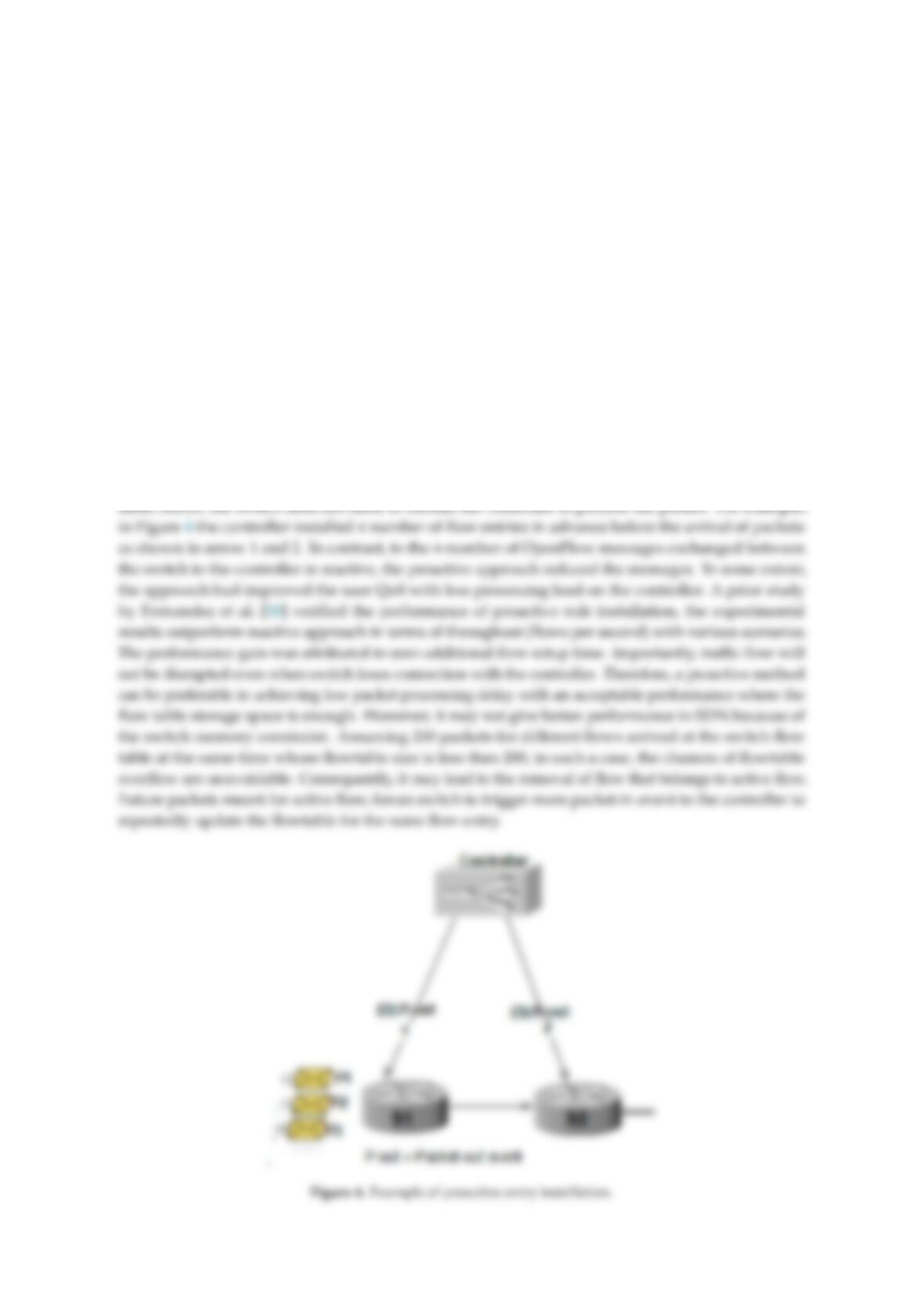
Future Internet 2020,12, 147 7 of 30
requirement is another bottleneck for real-time application in SDN. Packets must be delivered to the
desired destination with less delay guaranteed to avert declining QoS. This is necessary in order to
adhere to the fine-grained traffic engineering delay requirement by CGN. A long delay will result
in traffic congestion and increases packet losses, which can affect the performance of the network.
In a study by Sharma et al. [
29
], the experiment results carried on the small-scale network with
(6 and 14 switches) showed the possibility to meet the demand of carrier grade network CGN delay
requirement. The same experiment reported that the delay also depends on the number of flow
rules needed to modify or install in the affected switch. In the worst case, time can reach up to
300 milliseconds in 14 switches topology setting. Hence, it is challenging to meet the demand of
the (CGN) delay budget in large scale networks. Additionally, the presence of a large number of
flows introduced an extra processing load on both the controller and switch buffer. Therefore, using a
reactive approach for all flows setting may not give the desire performance in large scale networks.
2.3.2. Proactive Flow Table Allocation
In contrast to reactive, proactive handles the incoming packet faster because the controller can
install forwarding rules in advance before the flow arrival. Incoming flow whose packet headers
information matches an existing entry is processed according to the instruction defined in the flow
Future Internet 2020, 12, x FOR PEER REVIEW 7 of 30
requirement is another bottleneck for real-time application in SDN. Packets must be delivered to the
desired destination with less delay guaranteed to avert declining QoS. This is necessary in order to
adhere to the fine-grained traffic engineering delay requirement by CGN. A long delay will result in
traffic congestion and increases packet losses, which can affect the performance of the network. In a
study by Sharma et al. [29], the experiment results carried on the small-scale network with (6 and 14
switches) showed the possibility to meet the demand of carrier grade network CGN delay
requirement. The same experiment reported that the delay also depends on the number of flow rules
needed to modify or install in the affected switch. In the worst case, time can reach up to 300
milliseconds in 14 switches topology setting. Hence, it is challenging to meet the demand of the
(CGN) delay budget in large scale networks. Additionally, the presence of a large number of flows
introduced an extra processing load on both the controller and switch buffer. Therefore, using a
reactive approach for all flows setting may not give the desire performance in large scale networks.
2.3.2. Proactive Flow Table Allocation
In contrast to reactive, proactive handles the incoming packet faster because the controller can
install forwarding rules in advance before the flow arrival. Incoming flow whose packet headers
information matches an existing entry is processed according to the instruction defined in the flow
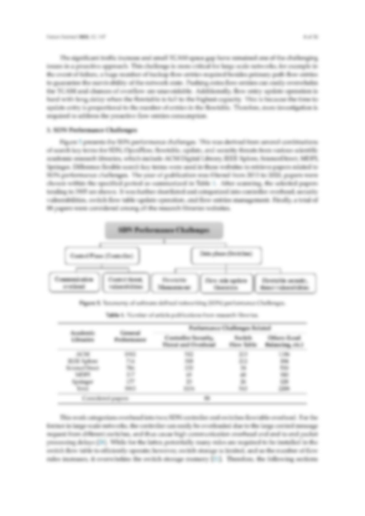
Future Internet 2020, 12, x FOR PEER REVIEW 8 of 30
The significant traffic increase and small TCAM space gap have remained one of the challenging
issues in a proactive approach. This challenge is more critical for large scale networks, for example
in the event of failure, a huge number of backup flow entries required besides primary path flow
faster than existing solutions with a flowtable size of 1000 and operation time by 15 ms and 60%
respectively.
Future Internet 2020, 12, x FOR PEER REVIEW 13 of 30
in a way that satisfies policies according to the device capacity. Rule caching is another method to
limit the number of concurrent forwarding rules in switch and reduce overhead switch to the
controller. Machine learning techniques are quite effective to predict the traffic flow pattern and select
the right flow to be installed in the switch flowtable. These proposals are detailed in the following
sections.
4.1. Timeout and Eviction Mechanisms
To overcome the limitation of the switch flow table storage (TCAM), OpenFlow allowed the use
of a timeout mechanism to determine the life span of forwarding entry in the switch flow table [52].
When no packet matches an entry within its timeout period, it will cause an entry to be evicted from
the flow table to free space for new incoming packets. Currently, there are two major methods for the
OpenFlow controller to install the timeout mechanism, idle and hard timeout. OpenFlow controller
usually configures flow entry with fixed idle timeout value in the scale of seconds across flows [56].