[1]
Fundamentals of Oscilloscope (Analog and Digital)
Shashidharan p, Former HOD, Dept. of Physics, Vartak College
The specific characteristic of a signal can be measured accurately by a variety of instruments:
for example the frequency or time period of a signal can be measured by a frequency meter,
voltage can be measured by volt meter etc. These instruments are limited to measuring only a
single characteristic.
Then, why an oscilloscope, which is not so accurate and expensive?
With an oscilloscope the user can visualize the signal of interest and also observe whether the
signal contains other properties that would not be made clear by most other instruments. For
example if an AC signal is riding on a DC signal or there is noise. Thus Oscilloscope is
indispensable tool for anyone designing, manufacturing or repairing electronic equipment or
even to scientists because with the proper sensor, an oscilloscope can measure all kinds of
phenomena.
The key to any good oscilloscope system is its ability to accurately reconstruct a waveform –
referred to as signal integrity.
Oscilloscopes can be classified – as analog and digital types. For many applications, either an
analog or digital oscilloscope will do. However, each type has unique characteristics that may
make it more or less suitable for specific applications. Digital oscilloscope can be further
classified into digital storage oscilloscopes (DSOs), digital phosphor oscilloscopes (DPOs)
and sampling oscilloscopes.
Analog oscilloscope (also called CRO, Cathode Ray Oscilloscope)
The CRO displays an input signal in VOLTS along the vertical or Y – axis as a function of
TIME along the horizontal or X – axis. The electronic circuit of a CRO is thus classified into
vertical and horizontal sections.
The vertical section has the following parts: The input selector, the input attenuator, the
vertical amplifier and the delay line. The horizontal section has the following parts: trigger
circuit, sweep generator, horizontal amplifier. The phosphor display called CRT(Cathode Ray
Tube) and graticule is common to both sections.
The Input Selector, Attenuator and Position
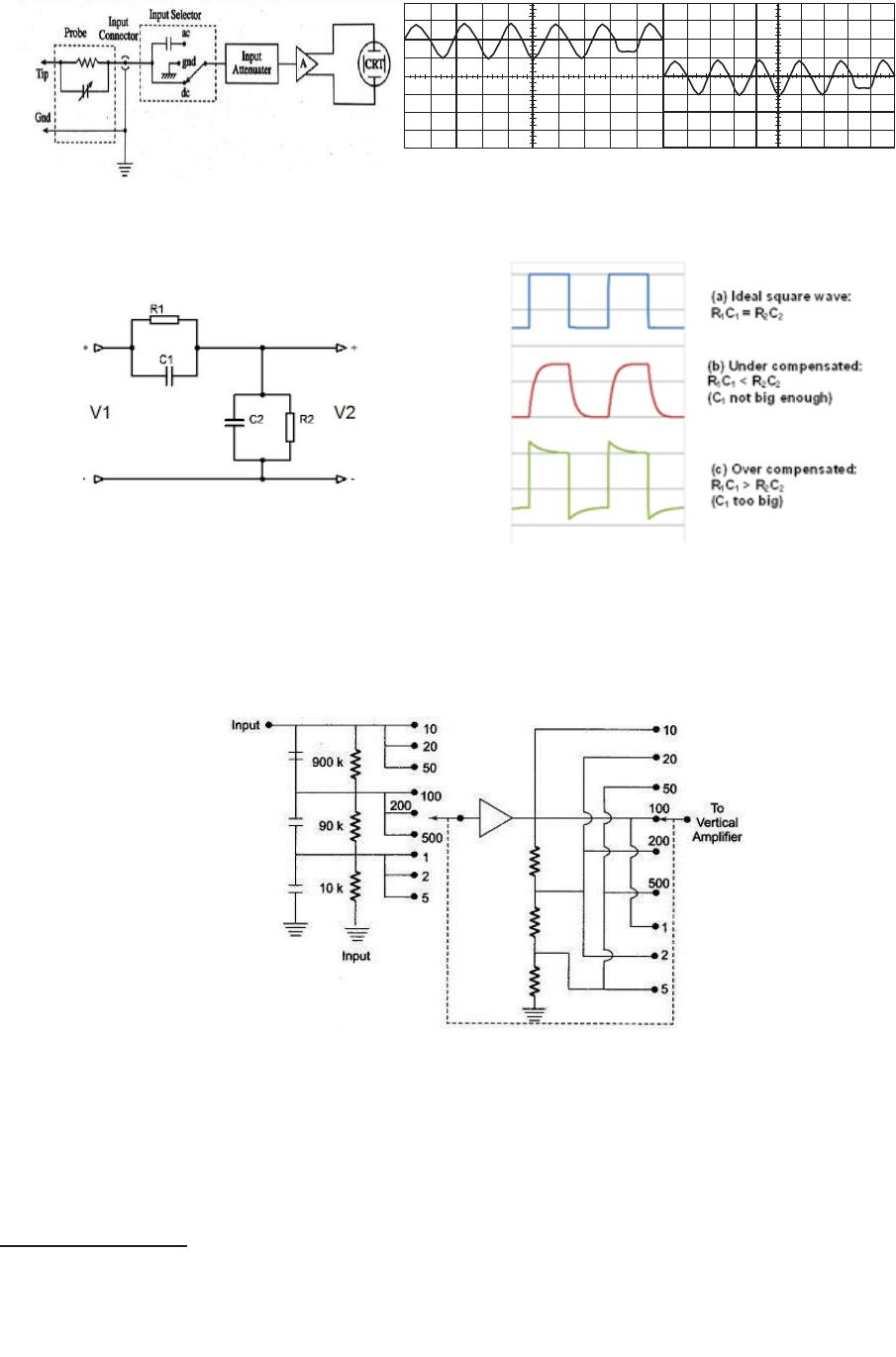
The input selector switch chooses direct coupling(dc), ground(gnd) or capacitor
coupling(ac).Generally the gnd is in between dc and ac (Fig.1). dc coupling allows the entire
signal (dc + ac) to be displayed on the screen (Fig.1a). ac coupling blocks the dc component
of a signal so that only the ac component centered around zero Volt is displayed (Fig.1b).
The ac coupling setting is useful when the entire signal (dc + ac) is too large. The ground
setting disconnects the input signal from the vertical system and a horizontal line on the
screen that represents zero volts can be seen in the auto trigger mode.
The input attenuator consists of a number of RC voltage dividers. The attenuator has to be a
compensated attenuator. A Compensated Attenuator is a simple two port network which
provides a constant attenuation over a wide range of frequencies (from DC to the highest
frequency the instrument can handle) (Fig.2).
[2]
Fig.1 Fig.1a Fig.1b
A compensated attenuator has to be critically compensated (R1C1 = R2C2). An under
compensated or over compensated attenuator will distort the waveform as shown in Fig.2a.
Fig.2 Fig.2a
A CRO has multi range compensated attenuator so that various voltage levels can be
measured by the same instrument (Fig.3). Input to compensated attenuator is from the input
selector. The switch that selects the attenuation is marked on CRO as Volts/Div. The
maximum voltage you can display on the screen is the volts/div setting multiplied by the
number of vertical divisions.
Fig.3
A test signal is provided on the oscilloscope by the manufacturer to check whether the
attenuator is critically compensated.
The vertical position control allows moving the waveform up and down exactly where one
wants it on the screen. It is marked on the CRO as V POS or with an up-down arrow (↕).
Vertical Amplifier
It amplifies the input signal, which is to be displayed on the screen of CRT. Vertical
amplifier is usually fixed gain. It is easy to design a fixed gain amplifier with large
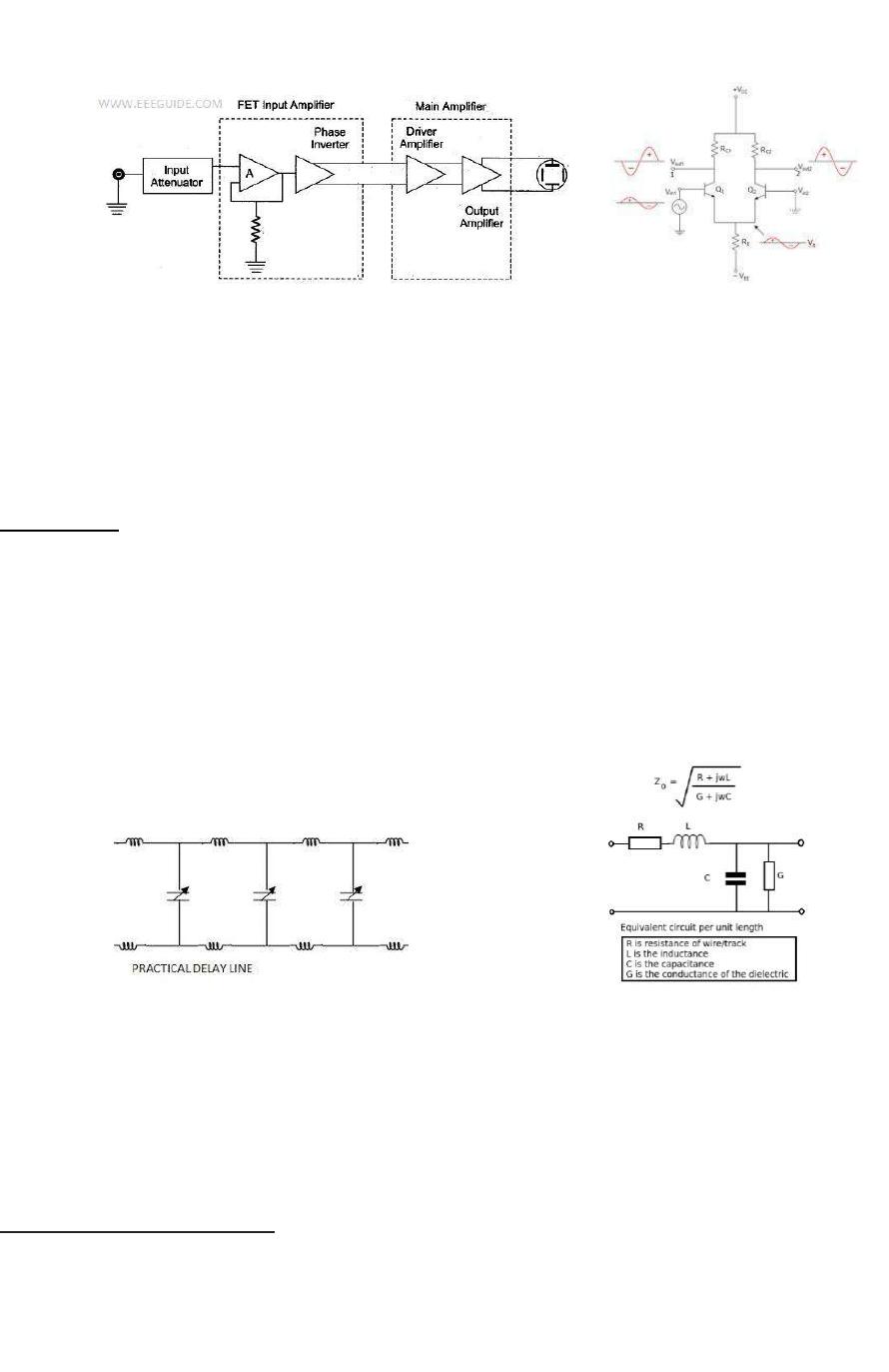
bandwidth. The vertical amplifier consists of a pre-amp and a main vertical amp. The pre-
[3]
amp is usually a FET input followed by a phase inverter or a paraphase amp which then
drives the main amp (Fig.4). A paraphase amp provides two output signals 180o out of phase
(Fig.4a).
Fig.4 Fig.4a
Vertical amplifier determines the sensitivity and bandwidth of the oscilloscope. The vertical
sensitivity is expressed in terms of V/Cm at the mid frequency. The sensitivity of an
oscilloscope is directly proportional to the gain of the vertical amplifier.
Some oscilloscopes provide a DSP arbitrary equalization filter used to improve the oscilloscope
response. This filter improves the frequency response, phase linearity, and provides a better
match between channels. It also decreases rise time and improves the step response.
Delay Line: A part of the input signal is used to start the horizontal sweep generator for
starting the horizontal deflection of the electron beam. It takes a certain amount of time
before the sweep is initiated. This results in the loss of the leading edge of the vertical input
signal. To overcome this problem the vertical signal is passed through a delay line so that the
vertical signal arrives at the Y- deflection plates exactly when the horizontal sweep is
initiated. The signal pick-off for horizontal sweep initiation should precede the delay line.
There are two types of delay lines: 1. Lumped parameter delay line (Fig.4b) and
2. Distributed parameter delay line (Fig.4c).
Fig.4b Fig.4c
The lumped parameter delay line consists of cascaded LC network. When the network is
terminated in its characteristic impedance Zo, it appears as a low pass filter. The pass-band is
defined as the range in which attenuation is zero. The upper limit of the pass-band is called
the cut-off frequency fc and delay time is given as approx. td ≈1/πfc = √LC.
The less careful adjustment and occupation of less space makes the distributed type co-axial
cable delay line more prospective.
Sweep or Ramp Generator
The CRO displays the vertical input signal as a function of time. This requires the electron
beam of the CRT to be moved across the screen with a constant velocity and returns rapidly
to the starting point on the left. This requires a linearly rising voltage which rises from a
minimum voltage to a maximum voltage and suddenly comes back to the minimum value.
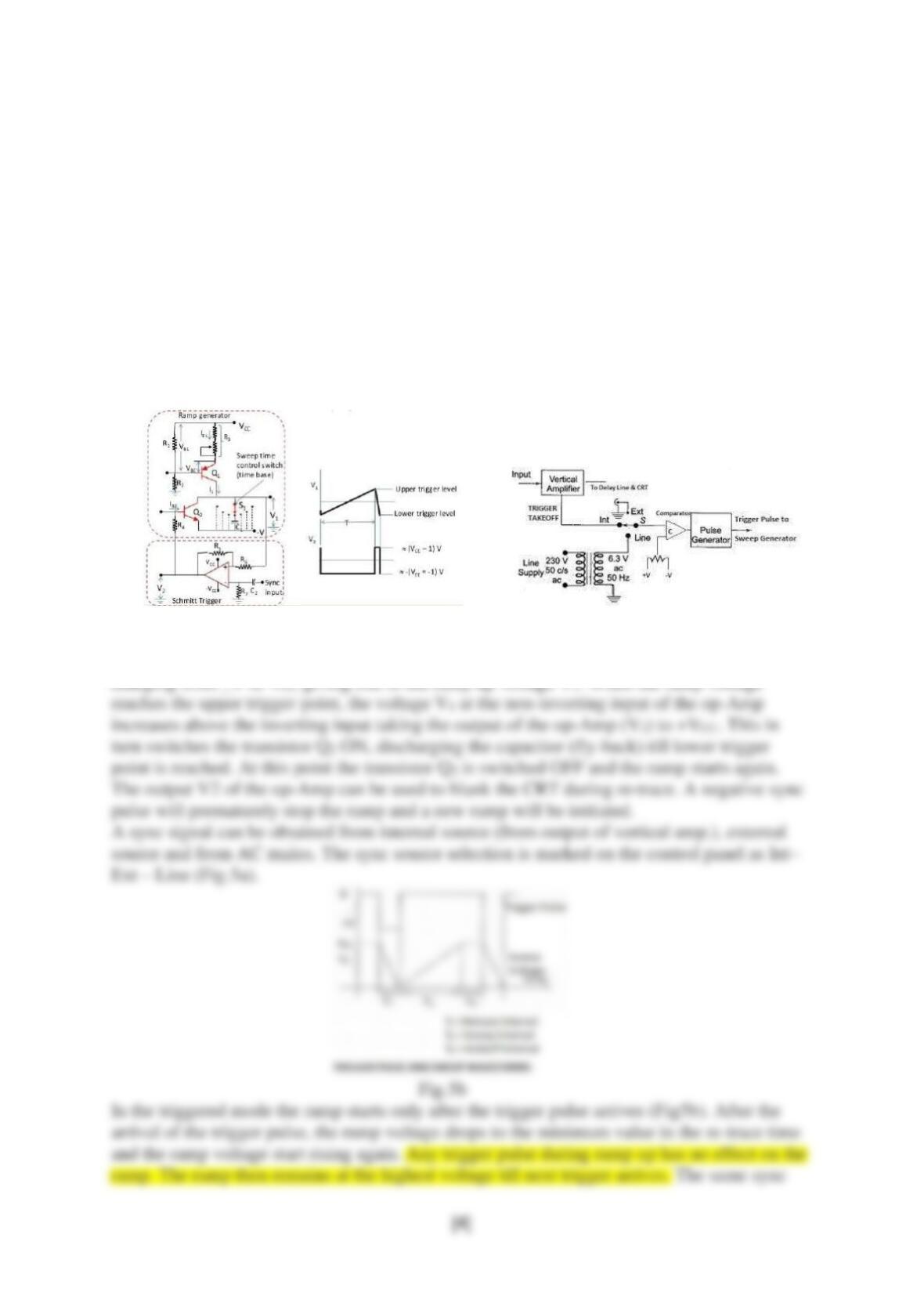
Such a waveform is generated by a sweep or ramp generator and the waveform is called a
saw-tooth wave. The linearly rising part of the saw tooth is called the run up ramp voltage.
During the ramp up the electron beam is swept from the left of the screen to the right. During
the re-trace or fly-back of the ramp the beam return from right to left of the screen. During
this return the beam is cut off using the control grid of the CRT (Voltage V2 in Fig.5).
A sweep generator is said to be free running if no external signal is used to start or stop the
ramp. A stable CRT display can be obtained only if the vertical frequency is an integral
multiple of the horizontal sweep frequency, otherwise the display becomes unstable. Thus the
sweep signal should be synchronized with the vertical input signal. This can be achieved by
the premature stoppage of the run-up ramp. For the first few sync pulses the ramp will remain
unsynchronized, eventually it get synchronized. The period of the sync signal should be
shorter than the free running ramp (Fig.5). The sweep time control on the CRO panel is
marked as TIME/DIV.
Fig.5 Fig.5a
In the absence of any sync pulse the inverting input of the op-Amp will be at Zero voltage,
thus taking its output (V2) to –VCC thus switching OFF transistor Q2. The capacitor will start