University of Houston
College of Technology
Computer Engineering Technology and Electrical Power
Technology
Freshman Laboratory
ELET 1400
Electrical Circuits I Laboratory
Experiment 3
Ohm’s Law, Kirchhoff’s Voltage and Current Laws, Variable Resistance,
Power, Power Dissipation, and Voltage Divider, and an Introduction to
Inductance and Basic Concepts of AC
2017 © – University of Houston, College of Technology ELET Labs

ELET 1400 2-27
Rev. 121410 LG © – 2011 University of Houston, College of Technology ELET Labs
2
Table of contents
1 Purpose ………………………………………………………………………………………………………. 3
2 Objectives …………………………………………………………………………………………………. 3
3 Equipment, Components and Software …………………………………………………….. 3
4 Pre-Lab ………………………………………………………………………………………………………. 4
4.1 Introduction to Ohm’s Law and Kirchhoff’s Voltage Law ………………….. 4
4.2 Simulation 1: Circuit with One Resistor ……………………………………………… 5
4.3 Simulation 2: Circuit with Two Resistors in Series …………………………… 6
4.4 Simulation 3: Circuit with Three Resistors in Series ……………………….. 7
4.5 Introduction to Variable Resistors (Potentiometer)…………………………. 9
4.6 Function Generator ……………………………………………………………………………. 10
4.7 Oscilloscope ……………………………………………………………………………………….. 12
4.8 Inductance …………………………………………………………………………………………. 15
5 Procedures ……………………………………………………………………………………………….. 17
5.1 Procedure 1 – Variable Resistance ……………………………………………………. 17
5.2 Introduction to Parallel Resistance ………………………………………………….. 17
5.3 Power ………………………………………………………………………………………………….. 21
5.4 Procedure 4 – Power Rating of Resistors …………………………………………. 22
6 Application: Voltage Divider ……………………………………………………………………. 22
7 Knowledge Evaluation ………………………………………………………………………………. 25
8 References ………………………………………………………………………………………………. 25
1 Purpose
This experiment is an introduction to the basic laws of electricity: Ohm’s
Law, Kirchhoff’s Voltage Law (KVL), and Kirchhoff’s Current Law (KCL). You
will learn about the concepts of variable Resistance, Power Dissipation and
the application of the Voltage Divider. Also, you will run simulations using the
program Multisim prior to the construction of the circuits.
2 Objectives
At the end of this experiment, you will know how to:
1. Simulate the performance of series resistance circuits.
2. Implement series resistance circuits of two or more resistors.
3. Measure voltage and current in series resistance circuits verifying
Ohm’s law and KVL using the DMM and power supply.
4. Measure voltage and current in parallel resistance circuits
verifying KCL using the DMM and power supply.
5. Solder various resistors on the PCB.
3 Equipment, Components and Software
• DMM
• Power Supply
• Soldering Gun/Solder
• Proto-board
• Resistors: 100Ω, 220Ω, 470Ω, 1KΩ, 10KΩ potentiometer.
• Multisim

ELET 1400 4-27
Rev. 121410 LG © – 2011 University of Houston, College of Technology ELET Labs
4
4 Pre-Lab
In the pre-lab section you will work in simulations and calculations before
your regular lab session. Performing these simulations you will learn how to
find the values of current through and voltage drop across each resistor.
Make sure that you draw each circuit, show the calculations, and write your
comments in your Pre Lab.
4.1 Introduction to Ohm’s Law and Kirchhoff’s Voltage Law
Ohm’s law is one of the most basic laws of electricity. One can find the
resistance value by current through or voltage drop across a resistor (as
long as the resistance value does not change with voltage – the components
that have resistance values that are independent of voltage are called ohmic
components). Ohm’s law is stated as
I
V
R=
(Eq. 1)
Another important relation is given by Kirchhoff’s Voltage Law, also known as
KVL. Kirchhoff was able to prove that the total voltage in a closed loop
(closed loop: a circuit that can be traced from a starting point without loss
of connectivity through its wires and components looping back to the
starting point) is equal to the sum of the individual voltage drops.
321 VVVE ++=
(Eq. 2)
Combining Ohm’s law and Kirchhoff’s law, we obtain a useful relation for
resistances in series. Since we know that the current flowing through series
of resistances in a closed loop is the same through each resistor, we have
ELET 1400 5-27
Rev. 121410 LG © – 2011 University of Houston, College of Technology ELET Labs
5
)RRR(IIRIRIRE321321 ++=++=
(Eq. 3)
In the following experiments, you will simulate and build circuits that
demonstrate these laws and show that they can be used to find voltage,
current, and resistor values.
4.2 Simulation 1: Circuit with One Resistor
In this simulation, you will familiarize yourself with
The Ohm’s Law using Multisim.
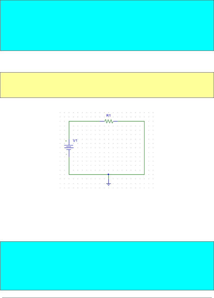
Figure 1 shows a basic circuit: power supply (E) connected to 1K resistor.
Figure 1 Basic circuit: one resistor connected to the power supply
Where:
V1 = 10V
R1 = 1KΩ
1. Use Ohm’s law (Eq. 1) to find the value of the current flowing in the
loop. Measure the value of the current using Multisim and compare
with the calculated value.
2. Are the two currents same? If not, calculate the % error between the
ELET 1400 6-27
Rev. 121410 LG © – 2011 University of Houston, College of Technology ELET Labs
6
measured and calculated values.
3. Show your calculations and write your observations in your Pre Lab.
4.3 Simulation 2: Circuit with Two Resistors in Series
In this simulation, you will verify KVL in a circuit with two
equal resistors in series.
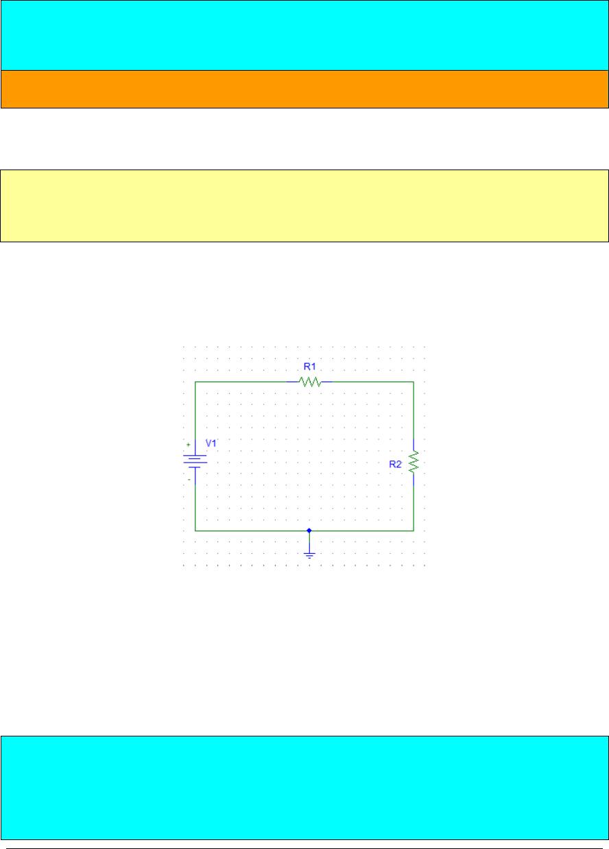
Figure 2 shows two resistors in series, you need to use KVL to perform the
following tasks (modify Eq. 3 to reflect two resistors in series):
Figure 2 Two resistors in series
Where
V1 = 10 V
R1 = R2 = 100 Ω
1. Find the total resistance RT by adding the resistances.
2. Draw the equivalent circuit in Multisim.
3. Use Ohm’s Law to find the total current through the resistors.
7
4. Redraw the original circuit and show the orientation of current flow
with an arrow, make sure to label V, I, R1, and R2.
5. Use the value of the calculated current and find the voltage drops
across R1 and R2.
6. Sum the voltage drops across R1 and R2.
7. Write your observations in your WS.