Data Modeling: Conceptual vs Logical vs
Physical Data Model
Data modeling is a technique to document a software system using entity
relationship diagrams (ER Diagram) which is a representation of the data structures
in a table for a company’s database. It is a very powerful expression of the
company’s business requirements. Data models are used for many purposes, from
high-level conceptual models, logical to physical data models and typically
represented by the entity-relationship diagram. It serves as a guide used by
database analysts and software developers in the design and implementation of a
system and the underlining database.
What is Entity Relationship Diagram?
An Entity Relationship Diagram (ERD) is a pictorial representation of the information
that can be captured by a database. Such a “picture” serves two purposes. It allows
database professionals to describe an overall design concisely yet accurately. An ER
Diagram can be easily transformed into the relational schema. There are three
components in ERD: Entities, Attributes, and Relationships.
Entities
The number of tables you need for your database – Entities is the basic objects of
ERDs. These are the tables of your database, i.e. students, courses, books, campus,
employees, payment, projects. A specific example of an entity is called an instance.
Each instance becomes a record or a row in a table.
Attributes
Information such as property, facts you need to describe each table – Attributes are
facts or descriptions of entities. They are also often nouns and become the columns
of the table. For example, for entity students, the attributes can be first name, last
name, email, address, and phone numbers.
• Primary Key Is An Attribute Or A Set Of Attributes That Uniquely Identifies An Instance
Of The Entity. For Example, For A Student Entity, Student Number Is The Primary Key
Since No Two Students Have The Same Student Number. We Can Have Only One
Primary Key In A Table. It Identifies Uniquely Every Row And It Cannot Be Null.
• Foreign Key Is A Key Used To Link Two Tables Together. Typically You Take The
Primary Key Field From One Table And Insert It Into The Other Table Where It Becomes
A Foreign Key (It Remains A Primary Key In The Original Table). We Can Have More
Than One Foreign Key In A Table.
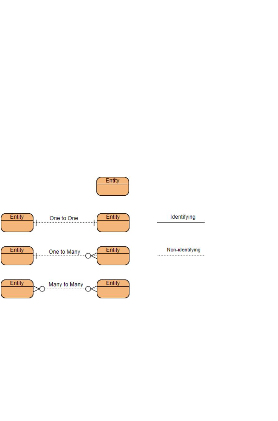
Relationships: How tables are linked together – Relationships are the associations
between the entities. Verbs often describe relationships between entities. We will
use Crow’s Foot Symbols to represent the relationships. Three types of relationships
are discussed in this lab. If you read or hear cardinality ratios, it also refers to types
of relationships.
Cardinality: it defines the possible number of occurrences in one entity which is
associated with the number of occurrences in another. For example, ONE team has