Lab #2
Compression Testing of Aluminum and Steel
Prepared By:
Eduardo Hernandez
CE 335 – Civil Engineering Materials I
Lab Division 004
September 14, 2021

Compression Testing of Aluminum and Steel Eduardo Hernandez
2
Synopsis/Abstract
The objective of the experiment was to determine the Young’s Modulus and Poisson’s ratio
of cylindrical samples of steel and aluminum by applying compression. To complete the objective,
familiarity was gained with two methods of strain testing machines. Eight compression loads were
applied to the steel and aluminum samples and electronic strain gauges were used to determine the
strain. Additionally, the same test was performed over the steel sample using DIC (Digital Image
Correlation. The Elastic Modulus was determined by determining the slope of the axial stress vs.
axial strain plot for each sample and was found to be 9.586 Mpsi for aluminum and 28.609 Mpsi
for steel. Consequently, Poisson’s ratio was calculated by determining the slope of the Transverse
Strain Vs. Axial Strain plot and was found to be 0.343 for aluminum and 0.2583 for steel.
As an attempt to eliminate bending from the measurements, two readings were recorded for
axial and transverse strain, using separate strain gauges, and the average was calculated between
them to represent a single value at each step.
Nonetheless, using stress and strain linear relationship, the experiment successfully
determined Youngs modulus and Poisson’s ratio for each material within acceptable percent
errors.
Compression Testing of Aluminum and Steel Eduardo Hernandez
3
Introduction
Applied compression and strain measurements were needed to determine the Elastic modulus
and Poisson’s ratio of an aluminum and a steel sample. Since both of these materials are considered
elastic, by applying compression to them stress is generated which subsequently causes
deformation on its shape. By measuring the ratio of deformation to its initial length we could
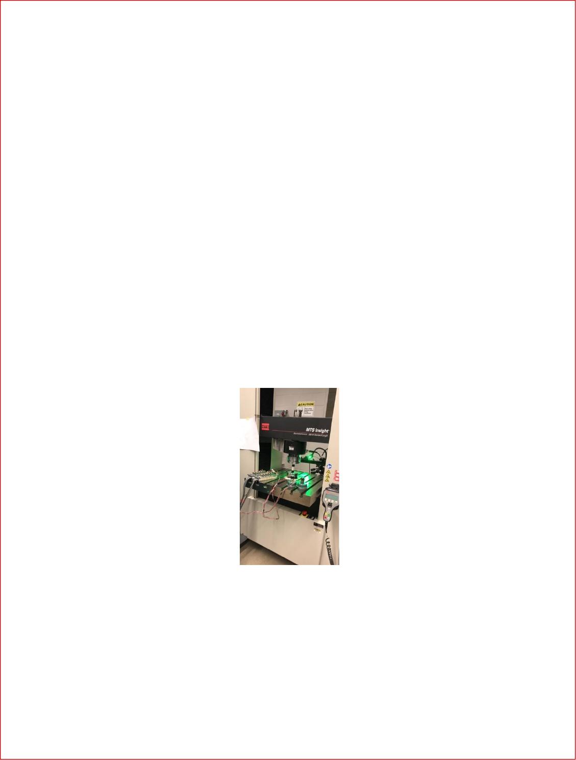
experimentally calculate the strain of the material. Fig. 1 shows the MTS testing machine loaded
with a sample while connected to strain gauges ready to perform a test on a steel sample. By the
nature of these materials they can present some bending that can skew the measurements. Thus,
by gathering two strain measurements at each step which were then averaged between them we
can cancel the bending readings. The experiment data was recorded at eight steps, starting at 1,000
pounds up to 8,000 pounds recording data every 1,000 pounds. After collecting the axial and
transversal strains and stresses the young modulus and poison’s ratio were calculated.
Fig. 1: MTS machine loaded to perform a test on a sample
Objectives
The objective was to experimentally determine the Modulus of elasticity of steel and aluminum by
measuring the axial stress and strain using the MTS machine with strain gage and with DIC (Digital

Compression Testing of Aluminum and Steel Eduardo Hernandez
4
Image Correlation). Additionally, using these same machines, Poisson’s ratio was also determined
by measuring transversal and longitudinal elongation.
Experimental Procedure
The lab collected strain measurements using two types of procedures. The first procedure
involves aluminum and steel samples to be compressed in the MTS machine while two strain gages
placed on the sample record the strains at every 1000 lbs intervals until it reaches 8000 lbs. The
stain gages are attached to the sample so that they are on opposite sides and diametrically opposite.
The strain measurements were recorded for each interval.
The second procedure involves just a steel sample which is again placed in the MTS machine
to be compressed. The test runs again with 8 steps starting at 1000 lbs until it reaches
8000 lbs but this time instead of the strain being measured by gauges it is measured using DIC.
This machine records strain measurements by comparing pictures taken throughout the test and
calculating the change in longitude. The dimensions of the cylindrical samples were recorded to
be 3 in (L) x 1 in (D).
Results
Upon applying compression to the aluminum and steel samples and recording the strain
gauge readings, the Elastic modulus and Poisson’s ratio were determined with the equations below.
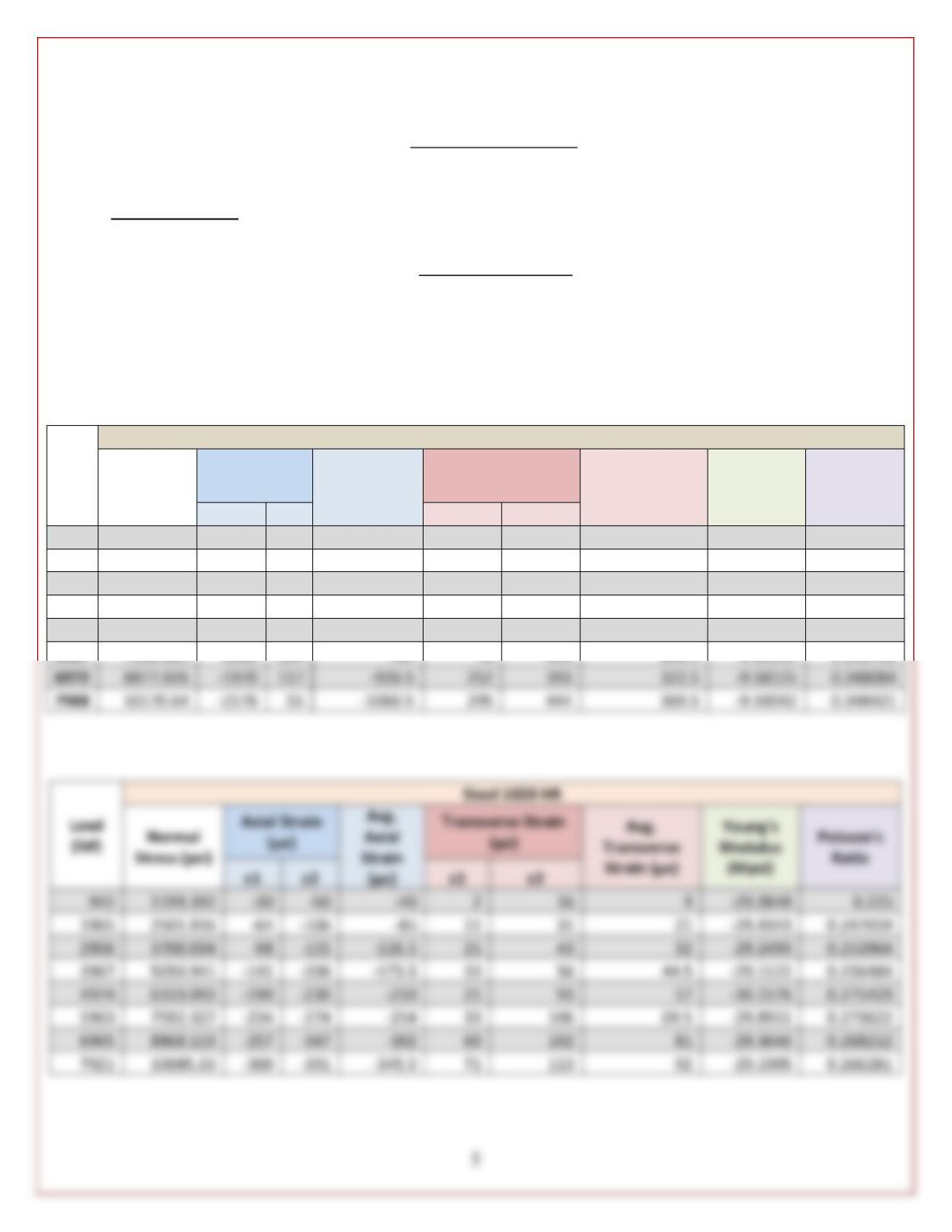
Table 1 and Table 2 summarize the strain values that were read from the electronic strain gauges
and the resulting calculated values for the aluminum and steel samples respectively.
𝐿𝑜𝑎𝑑 (𝑙𝑏𝑠)
𝑁𝑜𝑟𝑚𝑎𝑙 𝑆𝑡𝑟𝑒𝑠𝑠 =
𝐶𝑟𝑜𝑠𝑠 𝑆𝑒𝑐𝑡𝑖𝑜𝑛𝑎𝑙 𝐴𝑟𝑒𝑎 (𝑖𝑛. )
Young’s Modulus:
Compression Testing of Aluminum and Steel Eduardo Hernandez
𝑁𝑜𝑟𝑚𝑎𝑙 𝑆𝑡𝑟𝑒𝑠𝑠 (𝑝𝑠𝑖)
𝐸 =
𝐴𝑥𝑖𝑎𝑙 𝑆𝑡𝑟𝑎𝑖𝑛
Poisson’s Ratio:
𝑇𝑟𝑎𝑛𝑠𝑣𝑒𝑟𝑠𝑒 𝑆𝑡𝑟𝑎𝑖𝑛
𝑉 = <<
𝐴𝑥𝑖𝑎𝑙 𝑆𝑡𝑟𝑎𝑖𝑛
Table 1: Recorded axial and transverse strains along with resulting calculated values for
Young’s modulus and Poisson’s Ratio at each step for the Aluminum sample.
Load
(lbs)
Aluminum
Normal
Stress (psi)
Axial Strain
(µε)
Avg. Axial
Strain (µε)
Transverse Strain
(µε)
Avg.
Transverse
Strain (µε)
Young’s
Modulus
(Mpsi)
Poisson’s
Ratio
ε1
ε2
ε1
ε2
1003
1277.059
-392
126
-133
–17
114
48.5
-9.60195
0.364662
2008
2556.665
-733
209
-262
–19
212
96.5
-9.75826
0.368321
3026
3852.823
-1055
257
-399
-4
292
144
-9.6562
0.360902
3980
5067.493
-1331
282
-524.5
16
361
188.5
-9.66157
0.35939
5016
6386.57
-1613
291
-661
44
430
237
-9.66198
0.358548
5987
7622.885
-1862
284
-789
72
491
281.5
-9.66145
0.356781
6972
8877.026
-1970
117
-926.5
252
393
322.5
-9.58125
0.348084
7988
10170.64
-2176
295
444
369.5
-9.59042
0.348421
Axial Strain
(µε)
Transverse Strain
(µε)
1199.392
1965
2501.916
0.247059
2906
3700.034
0.252964
3967
5050.941
44.5
0.256484
4974
6333.093
0.271429
5963
7592.327
106
69.5
0.273622
6965
8868.113
102
0.268212
7921
10085.33
113
0.266281