Chapter 8 Flow in Pipes
Piping Systems and Pump Selection
8-62C For a piping system that involves two pipes of different diameters (but of identical length, material,
and roughness) connected in series, (a) the flow rate through both pipes is the same and (b) the pressure
drop across smaller diameter pipe is larger.
8-63C For a piping system that involves two pipes of different diameters (but of identical length, material,
and roughness) connected in parallel, (a) the flow rate through the larger diameter pipe is larger and (b) the
pressure drop through both pipes is the same.
8-64C The pressure drop through both pipes is the same since the pressure at a point has a single value, and
the inlet and exits of these the pipes connected in parallel coincide.
8-65C Yes, when the head loss is negligible, the required pump head is equal to the elevation difference
between the free surfaces of the two reservoirs.
8-66C The pump installed in a piping system will operate at the point where the system curve and the
characteristic curve intersect. This point of intersection is called the operating point.
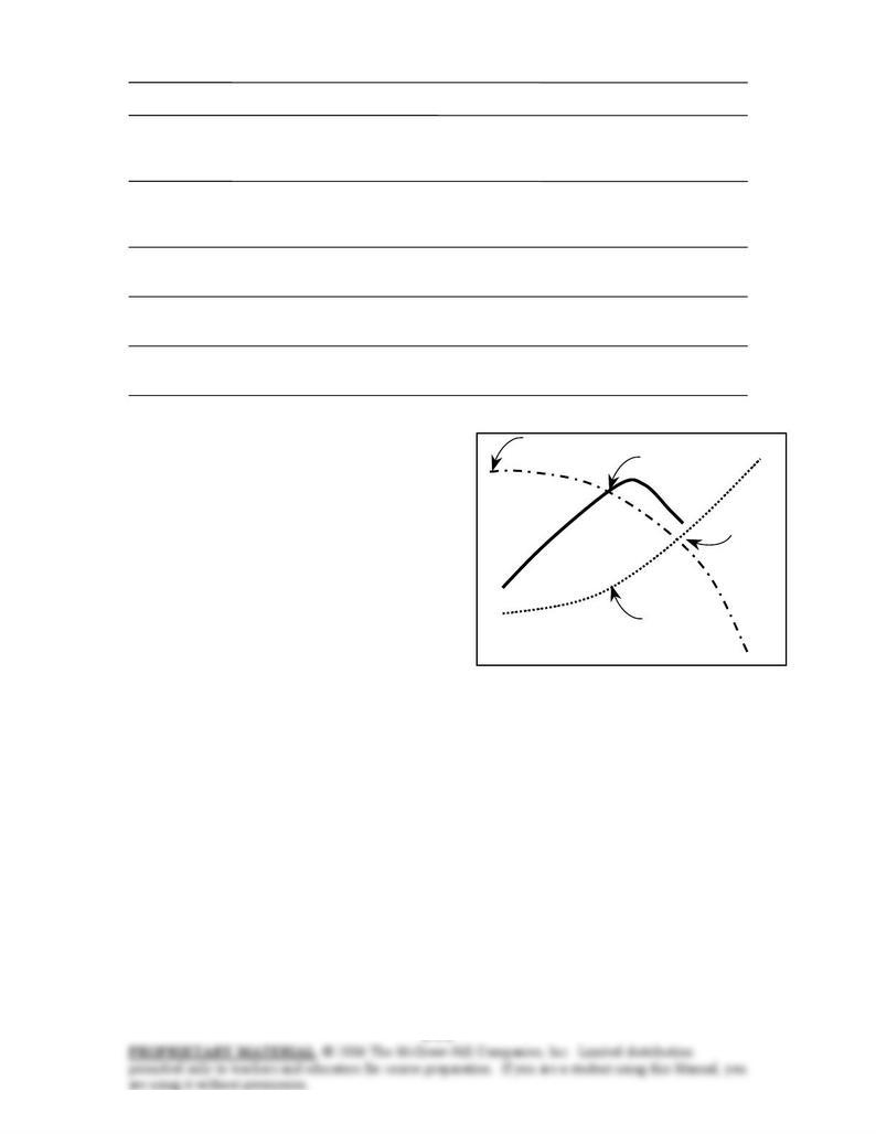
8-67C The plot of the head loss versus the flow rate
is called the system curve. The experimentally
determined pump head and pump efficiency versus
the flow rate curves are called characteristic curves.
The pump installed in a piping system will operate at
the point where the system curve and the
characteristic curve intersect. This point of
intersection is called the operating point. Operating
point
System
demand
curve
η
pump
hpump
Head
Flow rate
Chapter 8 Flow in Pipes
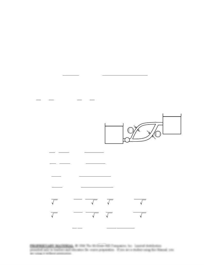
8-68 The pumping power input to a piping system with two parallel pipes between two reservoirs is given.
The flow rates are to be determined.
Assumptions 1 The flow is steady and incompressible. 2 The entrance effects are negligible, and thus the
flow is fully developed. 3 The elevations of the reservoirs remain constant. 4 The minor losses and the head
loss in pipes other than the parallel pipes are said to be negligible. 5 The flows through both pipes are
turbulent (to be verified).
Properties The density and dynamic viscosity of water at 20°C are ρ = 998 kg/m3 and µ = 1.002×10⁻³
kg/m⋅s. Plastic pipes are smooth, and their roughness is zero, ε = 0.
Analysis This problem cannot be solved directly since the velocities (or flow rates) in the pipes are not
known. Therefore, we would normally use a trial-and-error approach here. However, nowadays the
equation solvers such as EES are widely available, and thus below we will simply set up the equations to be
solved by an equation solver. The head supplied by the pump to the fluid is determined from
(1)
0.68
)m/s 81.9() kg/m(998
W 7000 upump,
23
motor–pump
upump,
inelect,
hgh
W
VV
&&
&=→=
η
ρ
We choose points A and B at the free surfaces of the two reservoirs. Noting that the fluid at both points is
open to the atmosphere (and thus PA = PB = Patm) and that the fluid velocities at both points are zero (VA =
VB =0), the energy equation for a control volume between these two points simplifies to
LABLB
B
B
B
A
A
A
Ahzzhhhz
g
V
g
P
hz
g
V
g
P+−=→++++=+++ )(
2
2 upump,e turbine,
2
upump,
2
α
ρ
α
ρ
or
L
hh +−= )29( upump, (2)
where
(4) (3) 2,1, LLL hhh ==
We designate the 3-cm diameter pipe by 1 and
the 5-cm diameter pipe by 2. The average
velocity, Reynolds number, friction factor, and
the head loss in each pipe are expressed as
(6)
4/m)05.0(
4/
(5)
4/m)03.0(
4/
2
2
2
2
2
2
2,
2
2
2
1
1
2
1
1
1,
1
1
ππ
ππ
VVV
VVV
&&&
&&&
=→==
=→==
V
D
A
V
V
D
A
V
c
c
2
1
25 m
3 cm
5 cm
Reservoir B
zB=2 m
Reservoir A
zA=2 m
Pump
(8)
kg/m10002.1
m) (0.05) kg/m998(
Re Re
(7)
kg/m10002.1
m) (0.03) kg/m998(
Re Re
3
2
3
2
22
2
3
1
3
1
11
1
s
VDV
s
VDV
⋅×
=→=
⋅×
=→=
−
−
µ
ρ
µ
ρ
Re
51.2
0log0.2
1
Re
51.2
7.3
/
log0.2
1
11111
1
1
+−=→
+−=
fff
D
f
ε
(9)
Re
51.2
0log0.2
1
Re
51.2
7.3
/
log0.2
1
22222
2
2
+−=→
+−=
fff
D
f
ε
(10
(11)
)m/s 81.9(2
m 03.0
m 25
22
2
1
11,
2
1
1
1
11,
V
fh
g
V
D
L
fh LL =→=

Chapter 8 Flow in Pipes
(12)
)m/s 81.9(2
m 05.0
m 25
22
2
2
22,
2
2
2
2
22,
V
fh
g
V
D
L
fh LL =→=
(13)
21
VVV
&&& +=
This is a system of 13 equations in 13 unknowns, and their simultaneous solution by an equation solver
gives
/sm 0.0146/sm 0.0037/sm 0.0183 333 === 21 , ,
VVV
&&& ,
V1 = 5.30 m/s, V2 = 7.42 m/s, m 19.5 2,1,
=
=
=
LLL hhh , hpump,u = 26.5 m
Re1 = 158,300, Re2 = 369,700, f1 = 0.0164, f2 = 0.0139
Note that Re > 4000 for both pipes, and thus the assumption of turbulent flow is verified.
Discussion This problem can also be solved by using an iterative approach, but it will be very time
consuming. Equation solvers such as EES are invaluable for this kind of problems.
Chapter 8 Flow in Pipes
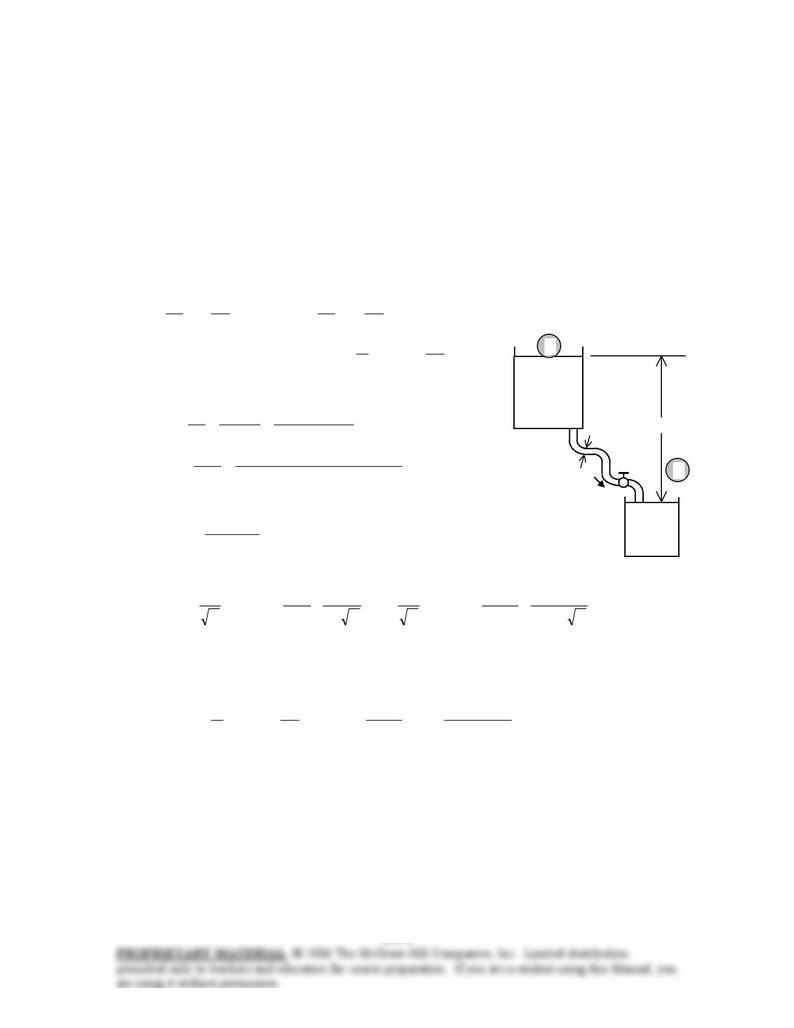
8-69E The flow rate through a piping system connecting two reservoirs is given. The elevation of the
source is to be determined.
Assumptions 1 The flow is steady and incompressible. 2 The entrance effects are negligible, and thus the
flow is fully developed. 3 The elevations of the reservoirs remain constant. 4 There are no pumps or
turbines in the piping system.
Properties The density and dynamic viscosity of water at 70°F are ρ = 62.30 lbm/ft3 and µ = 2.360 lbm/ft⋅h
= 6.556×10⁻⁴ lbm/ft⋅s. The roughness of cast iron pipe is ε = 0.00085 ft.
Analysis The piping system involves 120 ft of 2-in diameter piping, a well-rounded entrance (KL = 0.03), 4
standard flanged elbows (KL = 0.3 each), a fully open gate valve (KL = 0.2), and a sharp-edged exit (KL =
1.0). We choose points 1 and 2 at the free surfaces of the two reservoirs. Noting that the fluid at both points
is open to the atmosphere (and thus P1 = P2 = Patm), the fluid velocities at both points are zero (V1 = V2 =0),
the free surface of the lower reservoir is the reference level (z2 = 0), and that there is no pump or turbine
(hpump,u = hturbine = 0), the energy equation for a control volume between these two points simplifies to
LL hzhhz
g
V
g
P
hz
g
V
g
P=→++++=+++ 1e turbine,2
2
2
2
2
upump,1
2
1
1
1
2
2
α
ρ
α
ρ
where g
V
K
D
L
fhhhh LLLLL 2
2
minor,major,total,
+=+== ∑
since the diameter of the piping system is constant. The average
velocity in the pipe and the Reynolds number are
700,60
slbm/ft 10307.1
ft) ft/s)(2/12 64.7)(lbm/ft 3.62(
Re
ft/s 64.7
4/ft) 12/2(
/sft 10/60
4/
3
3
2
3
2
=
⋅×
==
====
−
µ
ρ
ππ
VD
D
A
V
c
VV
&&
which is greater than 4000. Therefore, the flow is turbulent. The
relative roughness of the pipe is
0051.0
ft 12/2
ft 00085.0
/==D
ε
The friction factor can be determined from the Moody chart, but to avoid the reading error, we determine it
from the Colebrook equation using an equation solver (or an iterative scheme),
1
2
10 ft3/min
z
120 ft
2 in
+−=→
+−=
fff
D
f700,60
51.2
7.3
0051.0
log0.2
1
Re
51.2
7.3
/
log0.2
1
ε
It gives f = 0.0320. The sum of the loss coefficients is
43.20.12.03.0403.04 exit,valve,elbow,entrance, =++×+=+++=
∑LLLLL KKKKK
Then the total head loss and the elevation of the source become
ft 1.23
)ft/s 2.32(2
ft/s) 64.7(
43.2
ft 2/12
ft 120
)0320.0(
22
2
2
=
+=
+= ∑g
V
K
D
L
fh LL
ft 23.1== L
hz1
Therefore, the free surface of the first reservoir must be 23.1 ft above the free surface of the lower reservoir
to ensure water flow between the two reservoirs at the specified rate.
Discussion Note that fL/D = 23.0 in this case, which is almost 10 folds of the total minor loss coefficient.
Therefore, ignoring the sources of minor losses in this case would result in an error of about 10%.
Chapter 8 Flow in Pipes
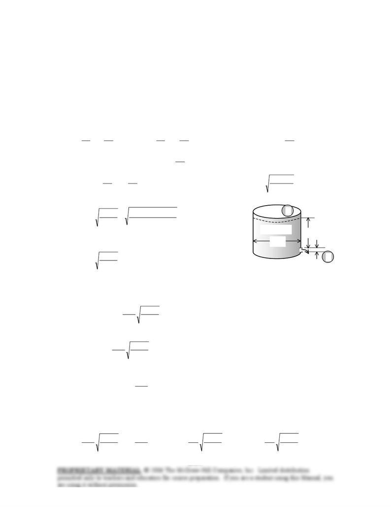
8-70 A water tank open to the atmosphere is initially filled with water. A sharp-edged orifice at the bottom
drains to the atmosphere. The initial velocity from the tank and the time required to empty the tank are to
be determined. √
Assumptions 1 The flow is uniform and incompressible. 2 The flow is turbulent so that the tabulated value
of the loss coefficient can be used. 3 The effect of the kinetic energy correction factor is negligible, α = 1.
Properties The loss coefficient is KL = 0.5 for a sharp-edged entrance.
Analysis (a) We take point 1 at the free surface of the tank, and point 2 at the exit of the orifice. We also
take the reference level at the centerline of the orifice (z2 = 0), and take the positive direction of z to be
upwards. Noting that the fluid at both points is open to the atmosphere (and thus P1 = P2 = Patm) and that
the fluid velocity at the free surface is very low (V1 ≅ 0), the energy equation for a control volume between
these two points (in terms of heads) simplifies to
2
22
2
2
21e turbine,2
2
2
2
2
upump,1
2
1
1
1
LL h
g
V
zhhz
g
V
g
P
hz
g
V
g
P+=→++++=+++
αα
ρ
α
ρ
where the head loss is expressed as g
V
Kh LL 2
2
=. Substituting and solving for V2 gives
L
LL K
gz
VKVgz
g
V
K
g
V
z+
=→+=→+=
2
1
22
2
21
2
2
2
2
21
2
)(2
22
α
αα
where α2 = 1. Noting that initially z1 = 2 m, the initial velocity is determined to be
1
3 m
Water tank 2 m
2
10 cm
m/s 5.11=
+
=
+
=0.51
m) 2)(m/s 81.9(2
1
22
1
2
L
K
gz
V
The average discharge velocity through the orifice at any given
time, in general, can be expressed as
L
K
gz
V+
=1
2
2
where z is the water height relative to the center of the orifice at that time.
(b) We denote the diameter of the orifice by D, and the diameter of the tank by D0. The flow rate of water
from the tank can be obtained by multiplying the discharge velocity by the orifice area,
L
K
gz
D
VAV +
== 1
2
4
2
2orifice
π
&
Then the amount of water that flows through the orifice during a differential time interval dt is
dt
K
gz
D
dtd
L
+
== 1
2
4
2
π
VV
& (1)
which, from conservation of mass, must be equal to the decrease in the volume of water in the tank,
dz
D
dzAdV 4
)(
2
0
tank
π
−=−= (2)
where dz is the change in the water level in the tank during dt. (Note that dz is a negative quantity since the
positive direction of z is upwards. Therefore, we used –dz to get a positive quantity for the amount of water
discharged). Setting Eqs. (1) and (2) equal to each other and rearranging,
dzz
g
K
D
D
dtdz
gz
K
D
D
dtdz
D
dt
K
gz
DLL
L
2/1
2
2
0
2
2
0
2
0
2
2
1
2
1
41
2
4
−
+
−=→
+
−=→−=
+
π
π