Chapter 8 Flow in Pipes
Review Problems
8-112 A compressor takes in air at a specified rate at the outdoor conditions. The useful power used by the
compressor to overcome the frictional losses in the duct is to be determined.
Assumptions 1 The flow is steady and incompressible. 2 The entrance effects are negligible, and thus the
flow is fully developed. 3 Air is an ideal gas. 4 The duct involves no components such as bends, valves,
and connectors, and thus minor losses are negligible. 5 The flow section involves no work devices such as
fans or turbines.
Properties The properties of air at 1 atm = 101.3 kPa and 15°C are ρ0 = 1.225 kg/m3 and µ = 1.802×10⁻⁵
kg/m⋅s. The roughness of galvanized iron surfaces is ε = 0.00015 m. The dynamic viscosity is independent
of pressure, but density of an ideal gas is proportional to pressure. The density of air at 95 kPa is
.
33
00 kg/m149.1) kg/m225.1)(3.101/95()/( ===
ρρ
PP
Analysis The average velocity and the Reynolds number are
m/s 594.8
4/m) (0.20
/sm 0.27
4/ 2
3
2====
ππ
D
A
V
c
VV
&&
5
5
3
10096.1
s kg/m10802.1
m) m/s)(0.20 )(8.594 kg/m(1.149
Re ×=
⋅×
== −
µ
ρ
h
VD
which is greater than 4000. Therefore, the flow is turbulent. The relative
roughness of the pipe is
105.7
m 20.0
m 105.1
/4
4−
−
×=
×
=D
ε
The friction factor can be determined from the Moody chart, but to avoid the reading error, we determine it
from the Colebrook equation using an equation solver (or an iterative scheme),
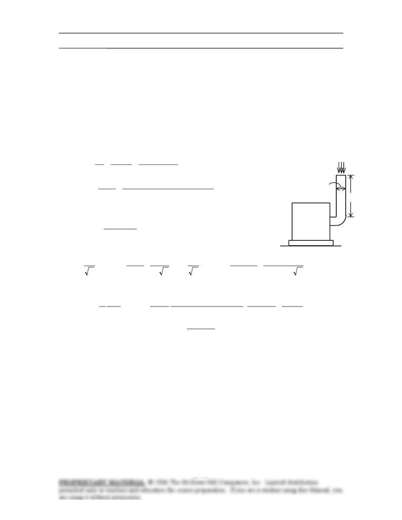
0.27 m3/s
95 kPa
Air
compressor
150 hp
20 cm
8 m
×
+
×
−=→
+−=
−
fff
D
f
h
5
4
10096.1
51.2
7.3
105.7
log0.2
1
Re
51.2
7.3
/
log0.2
1
ε
It gives f = 0.02109. Then the pressure drop in the duct and the required pumping power become
Pa 8.35
N/m 1
Pa 1
m/s kg1
N 1
2
m/s) 594.8)( kg/m149.1(
m 0.20
m 8
02109.0
222
23
2
=
⋅
==∆=∆ V
D
L
fPP L
ρ
W9.66=
⋅
=∆= /smPa 1
W1
)Pa 8.35)(/sm 27.0( 3
3
upump, PW
V
&
&
Discussion Note hat the pressure drop in the duct and the power needed to overcome it is very small
(relative to 150 hp), and can be disregarded.
The friction factor could also be determined easily from the explicit Haaland relation. It would
give f = 0.02086, which is very close to the Colebrook value. Also, the power input determined is the
mechanical power that needs to be imparted to the fluid. The shaft power will be more than this due to fan
inefficiency; the electrical power input will be even more due to motor inefficiency (but probably no more
than 20 W).
Chapter 8 Flow in Pipes
14-113 Air enters the underwater section of a circular duct. The fan power needed to overcome the flow
resistance in this section of the duct is to be determined.
Assumptions 1 The flow is steady and incompressible. 2 The entrance effects are negligible, and thus the
flow is fully developed. 3 Air is an ideal gas. 4 The duct involves no components such as bends, valves,
and connectors. 5 The flow section involves no work devices such as fans or turbines. 6 The pressure of air
is 1 atm.
Properties The properties of air at 1 atm and 15°C are ρ0 = 1.225 kg/m3 and µ = 1.802×10⁻⁵ kg/m⋅s. The
roughness of stainless steel pipes is ε = 0.000005 m.
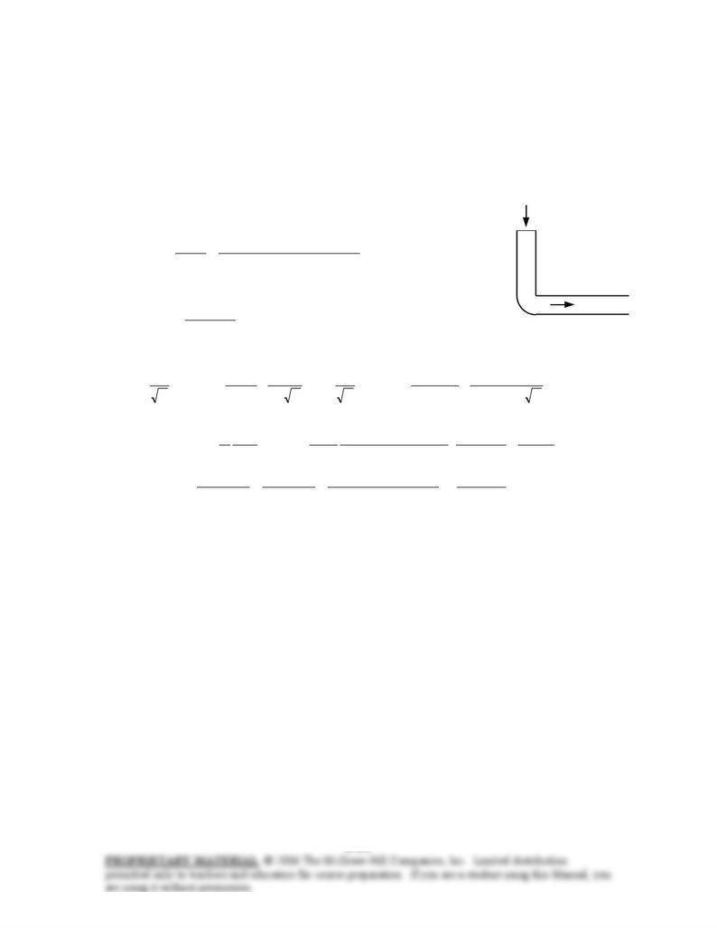
Analysis The volume flow rate and the Reynolds number are Air, 3 m/s
Air
River
/sm 0942.0]4/m) (0.20m/s)[ 3()4/( 322 ====
ππ
DVVAc
V
&
4
5
3
10079.4
s kg/m10802.1
m) m/s)(0.20 )(3 kg/m(1.225
Re ×=
⋅×
== −
µ
ρ
h
VD
which is greater than 4000. Therefore, the flow is turbulent. The
relative roughness of the pipe is
105.2
m 20.0
m 105
/5
6−
−
×=
×
=D
ε
The friction factor can be determined from the Moody chart, but to avoid the reading error, we determine it
from the Colebrook equation using an equation solver (or an iterative scheme),
×
+
×
−=→
+−=
−
fff
D
f
h
4
5
10079.4
51.2
7.3
105.2
log0.2
1
Re
51.2
7.3
/
log0.2
1
ε
It gives f = 0.02195. Then the pressure drop in the duct and the required pumping power become
Pa 07.9
N/m 1
Pa 1
m/s kg1
N 1
2
m/s) 3)( kg/m225.1(
m 0.2
m 15
02195.0
222
23
2
=
⋅
==∆=∆ V
D
L
fPP L
ρ
W1.4=
⋅
==
∆
== /smPa 1
W 1
62.0
)Pa 07.9)(/sm 0942.0(
3
3
motor–pumpmotor–pump
upump,
electric
ηη
P
W
W
V
&
&
&
Discussion The friction factor could also be determined easily from the explicit Haaland relation. It would
give f = 0.02175, which is sufficiently close to 0.02195. Assuming the pipe to be smooth would give
0.02187 for the friction factor, which is almost identical to the f value obtained from the Colebrook
relation. Therefore, the duct can be treated as being smooth with negligible error.
Chapter 8 Flow in Pipes
8-114 The velocity profile in fully developed laminar flow in a circular pipe is given. The radius of the
pipe, the average velocity, and the maximum velocity are to be determined.
Assumptions The flow is steady, laminar, and fully developed.
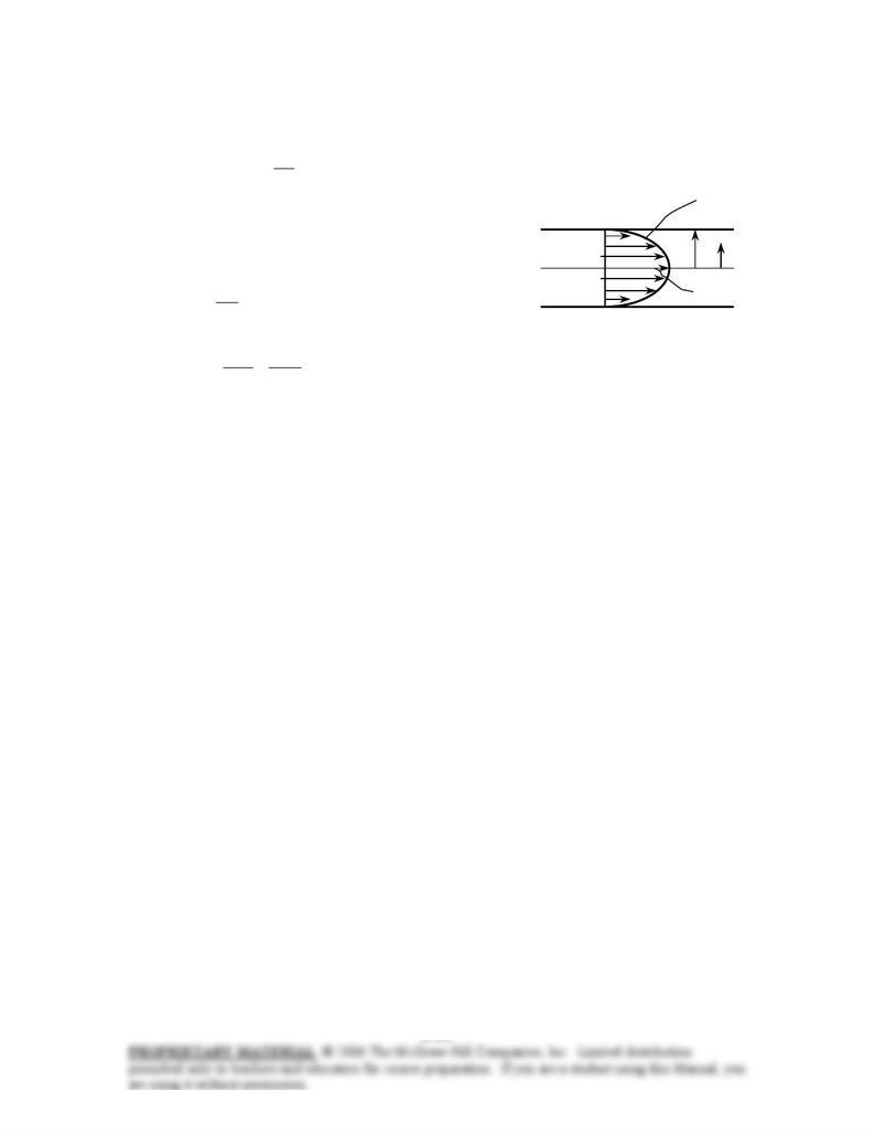
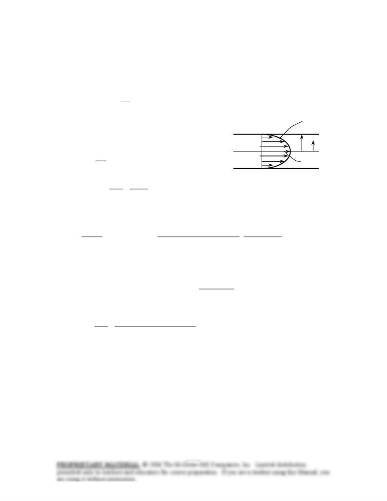
Analysis The velocity profile in fully developed laminar flow in a circular pipe is
−= 2
2
max 1)( R
r
uru
u(r)=umax(1-r2/R2)
The velocity profile in this case is given by
R
r
0
umax
)01.01(6)( 2
rru −=
Comparing the two relations above gives the pipe radius, the
maximum velocity, and the average velocity to be
m 0.10
100
1
2=→= RR
umax = 6 m/s
m/s 3=== 2
m/s 6
2
max
u
Vavg
Chapter 8 Flow in Pipes
8-115E The velocity profile in fully developed laminar flow in a circular pipe is given. The volume flow
rate, the pressure drop, and the useful pumping power required to overcome this pressure drop are to be
determined.
Assumptions 1 The flow is steady, laminar, and fully developed. 2 The pipe is horizontal.
Properties The density and dynamic viscosity of water at 40°F are ρ = 62.42 lbm/ft3 and µ = 3.74 lbm/ft⋅h
= 1.039×10⁻³ lbm/ft⋅s, respectively.
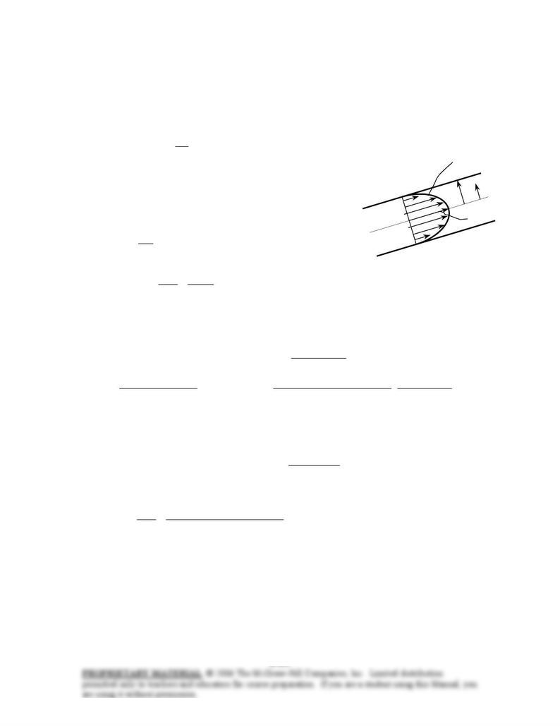
Analysis The velocity profile in fully developed laminar flow in a circular pipe is
−= 2
2
max 1)( R
r
uru
The velocity profile in this case is given by u(r)=umax(1-r2/R2)
R
r
0
umax
)6251(8.0)( 2
rru −=
Comparing the two relations above gives the pipe radius, the
maximum velocity, and the average velocity to be
ft 04.0
625
1
2=→= RR
umax = 0.8 ft/s
ft/s 4.0
2
ft/s 0.8
2
max ==== u
VV avg
Then the volume flow rate and the pressure drop become
/sft 0.00201 3
==== ]ft) (0.04ft/s)[ 4.0()( 22
ππ
RVVAc
V
&
⋅
⋅×
∆
=→
∆
=−lbf 1
ft/slbm 2.32
ft) s)(80lbm/ft 10039.1(128
ft) (0.08)(
/sft 0.00201
128
2
3
4
3
4
horiz
π
µ
π
P
L
DP
V
&
It gives
psi 0.0358==∆ 2
lbf/ft 16.5P
Then the useful pumping power requirement becomes
W 0.014=
⋅
=∆= ft/slbf 0.737
W 1
)lbf/ft 16.5)(/sft 00201.0( 23
upump, PW
V
&
&
Checking The flow was assumed to be laminar. To verify this assumption, we determine the Reynolds
number:
1922
slbm/ft 10039.1
ft) ft/s)(0.08 4.0)(lbm/ft 42.62(
Re 3
3
=
⋅×
== −
µ
ρ
VD
which is less than 2300. Therefore, the flow is laminar.
Discussion Note that the pressure drop across the water pipe and the required power input to maintain flow
is negligible. This is due to the very low flow velocity. Such water flows are the exception in practice
rather than the rule.
Chapter 8 Flow in Pipes
8-116E The velocity profile in fully developed laminar flow in a circular pipe is given. The volume flow
rate, the pressure drop, and the useful pumping power required to overcome this pressure drop are to be
determined.
Assumptions The flow is steady, laminar, and fully developed.
Properties The density and dynamic viscosity of water at 40°F are ρ = 62.42 lbm/ft3 and µ = 3.74 lbm/ft⋅h
= 1.039×10⁻³ lbm/ft⋅s, respectively.
Analysis The velocity profile in fully developed laminar flow in a circular pipe is
−= 2
2
max 1)( R
r
uru u(r) = umax(1-r2/R2)
The velocity profile in this case is given by
R
r
0
umax
)6251(8.0)( 2
rru −=
Comparing the two relations above gives the pipe radius, the
maximum velocity, the average velocity, and the volume flow rate to
be
ft 04.0
625
1
2=→= RR
umax = 0.8 ft/s
ft/s 4.0
2
ft/s 0.8
2
max ==== u
VV avg
/sft 0.00201 3
==== ]ft) (0.04ft/s)[ 4.0()( 22
ππ
RVVAc
V
&
For uphill flow with an inclination of 12°, we have θ = +12°, and
2
2
23 lbf/ft 1038
ft/slbm 2.32
lbf 1
12sin)ft 80)(ft/s 2.32)(lbm/ft 42.62(sin =
⋅
°=
θρ
gL
⋅
⋅×
−∆
=→
−∆
=−lbf 1
ft/slbm 2.32
ft) s)(80lbm/ft 10039.1(128
ft) (0.08)1038(
/sft 0.00201
128
)sin( 2
3
4
3
4
uphill
π
µ
πθρ
P
L
DgLP
&
V
It gives
psi 24.7lbf/ft 1043 2==∆P
Then the useful pumping power requirement becomes
ft/slbf 0.737
W 1
)lbf/ft 1043)(/sft 00201.0( 23
upump, W2.84=
⋅
=∆= PW
V
&
&
Checking The flow was assumed to be laminar. To verify this assumption, we determine the Reynolds
number:
1922
slbm/ft 10039.1
ft) ft/s)(0.08 4.0)(lbm/ft 42.62(
Re 3
3
=
⋅×
== −
µ
ρ
VD
which is less than 2300. Therefore, the flow is laminar.
Discussion Note that the pressure drop across the water pipe and the required power input to maintain flow
is negligible. This is due to the very low flow velocity. Such water flows are the exception in practice
rather than the rule.