Chapter 6 Momentum Analysis of Flow Systems
Review Problems
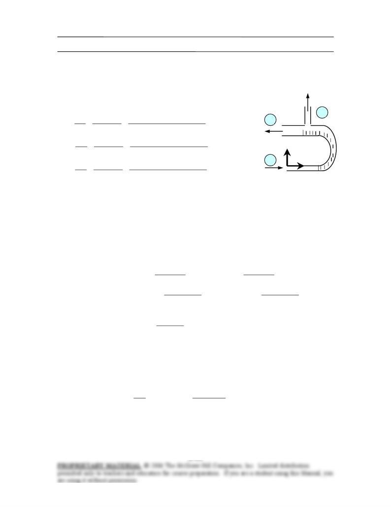
6-58 Water is flowing into and discharging from a pipe U-section with a secondary discharge section
normal to return flow. Net x- and z– forces at the two flanges that connect the pipes are to be determined.
Assumptions 1 The flow is steady and incompressible. 2 The weight of the U-turn and the water in it is
negligible. 4 The momentum-flux correction factor for each inlet and outlet is given to be
β
= 1.03.
Properties We take the density of water to be 1000 kg/m3.
F
R
x
F
Rz
30 kg/s
22 kg/s
3
2
1
8 kg/s
Analysis The flow velocities of the 3 streams are
m/s 3.15
]4/m) 05.0()[kg/m (1000
kg/s 30
)4/( 232
1
1
1
1
1====
ππρ
ρ
D
m
A
m&&
V
m/s 80.2
]4/m) 10.0()[ kg/m(1000
kg/s22
)4/( 232
2
2
2
2
2====
ππρ
ρ
D
m
A
m&&
V
m/s 3.11
]4/m) 03.0()[ kg/m(1000
kg/s8
)4/( 232
3
3
3
3
3====
ππρ
ρ
D
m
A
m&&
V
We take the entire U-section as the control volume. We designate the horizontal coordinate by x with the
direction of incoming flow as being the positive direction and the vertical coordinate by z. The momentum
equation for steady one-dimensional flow is
∑
∑
∑
−=
inout
VmVmF
r
&
r
&
r
ββ
. We let the x- and z- components
of the anchoring force of the cone be FRx and FRz, and assume them to be in the positive directions. Then
the momentum equations along the x and z axes become
0–0
)( )(
3333
1122221111222211
VmFVmF
VmVmAPAPFVmVmAPAPF
RzRz
RxRx
&&
&&&&
β
β
β
β
=→=+
+
−
−
−
=
→
−
−=++
Substituting the given values,
N 733−=−=
⋅
+
⋅
−
−−−−=
kN 0.733
m/skg 1000
kN 1
m/s) kg/s)(15.3 30(
m/skg 1000
kN 1
m/s) kg/s)(2.80 22(03.1
4
m) (0.10
]kN/m )100150[(
4
m) (0.05
]kN/m )100200[(
22
2
2
2
2
ππ
Rx
F
N 93.1=
⋅
=2
m/s kg1
N 1
m/s) 3 kg/s)(11.8(03.1
Rz
F
The negative value for FRx indicates the assumed direction is wrong, and should be reversed. Therefore, a
force of 733 N acts on the flanges in the opposite direction. A vertical force of 93.1 N acts on the flange in
the vertical direction.
Discussion To assess the significance of gravity forces, we estimate the weight of the weight of water in
the U-turn and compare it to the vertical force. Assuming the length of the U-turn to be 0.5 m and the
average diameter to be 7.5 cm, the mass of the water becomes
kg2.2m) (0.5
4
m) (0.075
) kg/m1000(
4
2
3
2
=====
ππ
ρρρ
L
D
ALm
V
whose weight is 2.2×9.81 = 22 N, which is much less than 93.1, but still significant. Therefore,
disregarding the gravitational effects is a reasonable assumption if great accuracy is not required.
Chapter 6 Momentum Analysis of Flow Systems
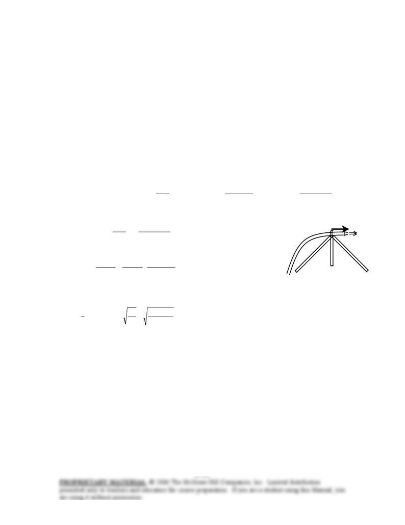
6-59 A fireman was hit by a nozzle held by a tripod with a rated holding force. The accident is to be
investigated by calculating the water velocity, the flow rate, and the nozzle velocity.
Assumptions 1 The flow is steady and incompressible. 2 The water jet is exposed to the atmosphere, and
thus the pressure of the water jet is the atmospheric pressure, which is disregarded since it acts on all
surfaces. 3 Gravitational effects and vertical forces are disregarded since the horizontal resistance force is
to be determined. 4 Jet flow is nearly uniform and thus the momentum-flux correction factor can be taken
to be unity,
β
≅ 1.
Properties We take the density of water to be 1000 kg/m3.
Analysis We take the nozzle and the horizontal portion of the hose as the system such that water enters the
control volume vertically and outlets horizontally (this way the pressure force and the momentum flux at
the inlet are in the vertical direction, with no contribution to the force balance in the horizontal direction,
and designate the entrance by 1 and the outlet by 2. We also designate the horizontal coordinate by x (with
the direction of flow as being the positive direction).
The momentum equation for steady one-dimensional flow is ∑
∑
∑
−=
inout
VmVmF
r
&
r
&
r
ββ
. We let
the horizontal force applied by the tripod to the nozzle to hold it be FRx, and assume it to be in the positive x
direction. Then the momentum equation along the x direction becomes
2
2
3
2
2
2
4
m) (0.05
)kg/m 1000(
N 1
m/skg 1
N) (1800
4
0VV
D
AVVVmVmF eRx
π
π
ρρ
=
⋅
→===−= &&
Solving for the water outlet velocity gives V = 30.3 m/s. Then the water flow rate becomes
D
= 5 cm
N
ozzle
F
Rx
Tripod
/sm 0.0595 3
==== m/s) (30.3
4
m) (0.05
4
2
2
π
π
V
D
AV
V
&
When the nozzle was released, its acceleration must have been
m/s 180
N 1
m/skg 1
kg 10
N 1800 2
2
nozzle
nozzle =
⋅
== m
F
a
Assuming the reaction force acting on the nozzle and thus its acceleration to remain constant, the time it
takes for the nozzle to travel 60 cm and the nozzle velocity at that moment were (note that both the distance
x and the velocity V are zero at time t = 0)
s
a
x
tatx 0816.0
m/s 180
m) 6.0(2
2
2
2
2
1===→=
V m/s 14.7=== s) 0816.0)(m/s 180( 2
at
Thus we conclude that the nozzle hit the fireman with a velocity of 14.7 m/s.
Discussion Engineering analyses such as this one are frequently used in accident reconstruction cases, and
they often form the basis for judgment in courts.
Chapter 6 Momentum Analysis of Flow Systems
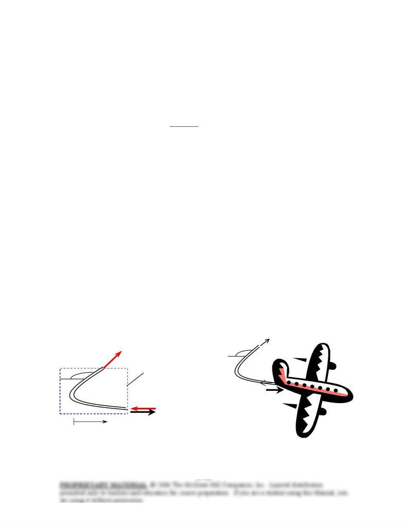
6-60 During landing of an airplane, the thrust reverser is lowered in the path of the exhaust jet, which
deflects the exhaust and provides braking. The thrust of the engine and the braking force produced after the
thrust reverser is deployed are to be determined. √EES
Assumptions 1 The flow of exhaust gases is steady and one-dimensional. 2 The exhaust gas stream is
exposed to the atmosphere, and thus its pressure is the atmospheric pressure. 3 The velocity of exhaust
gases remains constant during reversing. 4 Jet flow is nearly uniform and thus the momentum-flux
correction factor can be taken to be unity,
β
≅ 1.
Analysis (a) The thrust exerted on an airplane is simply the momentum flux of the combustion gases in the
reverse direction,
N 4500=
⋅
== 2
m/s kg1
N 1
m/s) kg/s)(25018(
exexVm
&
Thrust
(b) We take the thrust reverser as the control volume such that it cuts through both exhaust streams
normally and the connecting bars to the airplane, and the direction of airplane as the positive direction of x
axis. The momentum equation for steady one-dimensional flow in the x direction reduces to
∑∑∑ −=
inout
VmVmF
r
&
r
&
r
ββ
→ )20cos1( )( )cos20( iRxRx VmFVmVmF &&& °+=→
−
−
°
=
Substituting, the reaction force is determined to be
N 8729m/s) kg/s)(25018)(20cos1(
=
°+=
Rx
F
The breaking force acting on the plane is equal and opposite to this force,
N 8729=
breaking
F
Therefore, a braking force of 8729 N develops in the opposite direction tot flight.
Discussion This problem can be solved more generally by measuring the reversing angle from the direction
of exhaust gases (α = 0 when there is no reversing). When α < 90°, the reversed gases are discharged in the
negative x direction, and the momentum equation reduces to
)cos1( )( )cos( iRxRx VmFVmVmF &&&
α
α
−
=
→−−−=
This equation is also valid for α >90° since cos(180°–α) = – cosα. Using α = 160°, for example, gives
)20cos1( )160cos1( iiRx VmVmF && +=−= , which is identical to the solution above.
F
Rx
250 m/s
160°
Vm
&
Vm
&Control
volume
F
R
x
α = 160°
x
Chapter 6 Momentum Analysis of Flow Systems
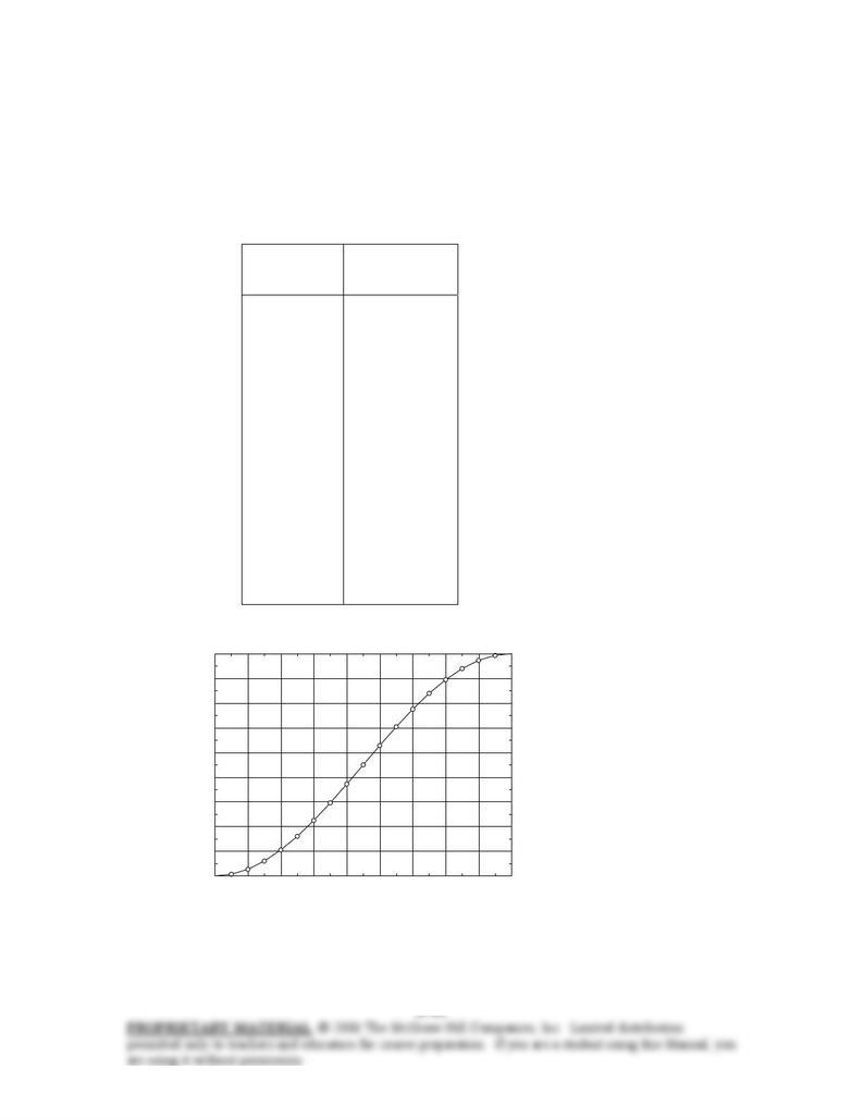
6-61 Problem 6-60 reconsidered. The effect of thrust reverser angle on the braking force exerted on the
airplane as the reverser angle varies from 0 (no reversing) to 180° (full reversing) in increments of 10° is to
be investigated.
V_jet=250 “m/s”
m_dot=18 “kg/s”
F_Rx=(1-cos(alpha))*m_dot*V_jet “N”
Reversing
angle,
α
°
Braking force
Fbrake, N
0
10
20
30
40
50
60
70
80
90
100
110
120
130
140
150
160
170
180
0
68
271
603
1053
1607
2250
2961
3719
4500
5281
6039
6750
7393
7947
8397
8729
8932
9000
02040 60 80 100 120 140 160 180
0
1000
2000
3000
4000
5000
6000
7000
8000
9000
α
,
°
Fbrake, N