Chapter 6 Momentum Analysis of Flow Systems
Angular Momentum Equation
6-44C The angular momentum equation is obtained by replacing B in the Reynolds transport theorem by
the total angular momentum sys
H
r
, and b by the angular momentum per unit mass Vr
r
r
×.
6-45C The angular momentum equation in this case is expressed as I Vmr
r
&
r
r
×−=
α
where
α
r
is the angular
acceleration of the control volume, and
r
r
is the position vector from the axis of rotation to any point on the
line of action of
F
r
.
6-46C The angular momentum equation in this case is expressed as I Vmr
r
&
r
r
×−=
α
where
α
r
is the angular
acceleration of the control volume, and
r
r
is the position vector from the axis of rotation to any point on the
line of action of
F
r
.
Chapter 6 Momentum Analysis of Flow Systems
6-47 Water is pumped through a piping section. The moment acting on the elbow for the cases of
downward and upward discharge is to be determined.
Assumptions 1 The flow is steady and incompressible. 2 The water is discharged to the atmosphere, and
thus the gage pressure at the outlet is zero. 3 Effects of water falling down during upward discharge is
disregarded. 4 Pipe outlet diameter is small compared to the moment arm, and thus we use average values
of radius and velocity at the outlet.
Properties We take the density of water to be 1000 kg/m3.
Analysis We take the entire pipe as the control volume, and designate the inlet by 1 and the outlet by 2. We
also take the x and y coordinates as shown. The control volume and the reference frame are fixed.
The conservation of mass equation for this one-inlet one-outlet steady flow system is
, and Vmmm &&& == 21 VV =
=
21 since Ac = constant. The mass flow rate and the weight of the horizontal
section of the pipe are
kg/s24.45)m/s 4](4/m) 12.0()[ kg/m(1000 23 ===
πρ
VAm c
&
N/m 3.294
m/s kg1
N 1
)m/s 81.9)(m 2)( kg/m(15 2
2=
⋅
== mgW
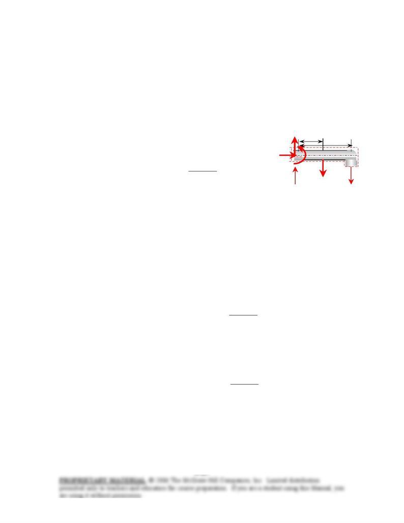
(a) Downward discharge: To determine the moment acting on the pipe at point A, we need to take the
moment of all forces and momentum flows about that point. This is a steady and uniform flow problem,
and all forces and momentum flows are in the same plane. Therefore, the angular momentum equation in
this case can be expressed as
∑
∑
∑−=
inout
VmrVmrM && where r is the moment arm, all moments in the
counterclockwise direction are positive, and all in the clockwise direction are negative.
2
Vm
r
&
1
Vm
r
&
r2 = 1 m r1 = 2 m
M
A
•
A
W
The free body diagram of the pipe section is given in the figure. Noting that the moments of all
forces and momentum flows passing through point A are zero, the only force that will yield a moment about
point A is the weight W of the horizontal pipe section, and the only momentum flow that will yield a
moment is the outlet stream (both are negative since both moments are in the clockwise direction). Then
the angular momentum equation about point A becomes
221 VmrWrM A&
−=−
Solving for MA and substituting,
mN 70.0 ⋅−=
⋅
=−= 2
221 m/s kg1
N 1
m/s) kg/s)(4m)(45.54 (2–N) m)(294.3 1(
VmrWrM A&
The negative sign indicates that the assumed direction for MA is wrong, and should be reversed. Therefore,
a moment of 70 N⋅m acts at the stem of the pipe in the clockwise direction.
(b) Upward discharge: The moment due to discharge stream is positive in this case, and the moment
acting on the pipe at point A is
mN 659 ⋅=
⋅
+=+= 2
221 m/skg 1
N 1
m/s) kg/s)(4 m)(45.54 (2N) m)(294.3 1(VmrWrM A&
Discussion Note direction of discharge can make a big difference in the moments applied on a piping
system. This problem also shows the importance of accounting for the moments of momentums of flow
streams when performing evaluating the stresses in pipe materials at critical cross-sections.
Chapter 6 Momentum Analysis of Flow Systems
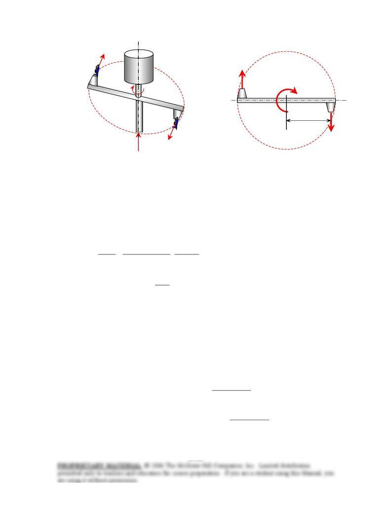
6-48E A two-armed sprinkler is used to generate electric power. For a specified flow rate and rotational
speed, the power produced is to be determined.
gal/s 8
total =m
&jet
V
jet
V
ω
Electric
generator
r
Vmnozzle
&
r
Vmnozzle
&
r = 2 ft
•
M
shaft
Assumptions 1 The flow is cyclically steady (i.e., steady from a frame of reference rotating with the
sprinkler head). 2 The water is discharged to the atmosphere, and thus the gage pressure at the nozzle outlet
is zero. 3 Generator losses and air drag of rotating components are neglected. 4 The nozzle diameter is
small compared to the moment arm, and thus we use average values of radius and velocity at the outlet.
Properties We take the density of water to be 62.4 lbm/ft3.
Analysis We take the disk that encloses the sprinkler arms as the control volume, which is a stationary
control volume. The conservation of mass equation for this steady flow system is m. Noting
that the two nozzles are identical, we have
mm &&& == 21
2/
nozzle mm &&
=
or since the density of water
is constant. The average jet outlet velocity relative to the nozzle is
2/
nozzle
total
VV
&& =
ft/s 2.392
gal 480.7
ft 1
]4/ft) 12/5.0([
gal/s 4 3
2
jet
nozzle
jet =
==
π
A
V
V
&
The angular and tangential velocities of the nozzles are
ft/s 52.36 rad/s)ft)(26.18 2(
rad/s26.18
s 60
min 1
rev/min)250(22
nozzle ===
=
==
ω
ππω
rV
n
&
The velocity of water jet relative to the control volume (or relative to a fixed location on earth) is
ft/s 8.33936.522.392
nozzlejet
=
−=−= VVVr
The angular momentum equation can be expressed as ∑
∑
∑
−=
inout
VmrVmrM && where all
moments in the counterclockwise direction are positive, and all in the clockwise direction are negative.
Then the angular momentum equation about the axis of rotation becomes
r
VmrM nozzleshaft 2&
−=− or r
VmrM totalshaft &
=
Substituting, the torque transmitted through the shaft is determined to be
ftlbf 1409
ft/slbm 32.2
lbf 1
ft/s) .8lbm/s)(339 ft)(66.74 2( 2
totalshaft ⋅=
⋅
== r
VmrM &
since . Then the power generated becomes lbm/s 74.66)/sft 480.7/8)(lbm/ft (62.4 33
totaltotal ===
V
&
&
ρ
m
kW 50.0=
⋅
⋅=== ft/slbf 737.56
kW1
ft)lbf 09 rad/s)(1418.26(2 shaftshaft MMnW
ωπ
&
&
Therefore, this sprinkler-type turbine has the potential to produce 50 kW of power.