Chapter 6 Momentum Analysis of Flow Systems
Chapter 6
MOMENTUM ANALYSIS OF FLOW SYSTEMS
Newton’s Laws and Conservation of Momentum
6-1C Newton’s first law states that “a body at rest remains at rest, and a body in motion remains in motion
at the same velocity in a straight path when the net force acting on it is zero.” Therefore, a body tends to
preserve its state or inertia. Newton’s second law states that “the acceleration of a body is proportional to
the net force acting on it and is inversely proportional to its mass.” Newton’s third law states “when a body
exerts a force on a second body, the second body exerts an equal and opposite force on the first.”
6-2C Since momentum ( mV
r
) is the product of a vector (velocity) and a scalar (mass), momentum must be
a vector that points in the same direction as the velocity vector.
6-3C The conservation of momentum principle is expressed as “the momentum of a system remains
constant when the net force acting on it is zero, and thus the momentum of such systems is conserved”. The
momentum of a body remains constant if the net force acting on it is zero.
6-4C Newton’s second law of motion, also called the angular momentum equation, is expressed as “the
rate of change of the angular momentum of a body is equal to the net torque acting it.” For a non-rigid
body with zero net torque, the angular momentum remains constant, but the angular velocity changes in
accordance with I
ω
= constant where I is the moment of inertia of the body.
6-5C No. Two rigid bodies having the same mass and angular speed will have different angular
momentums unless they also have the same moment of inertia I.
Linear Momentum Equation
6-6C The relationship between the time rates of change of an extensive property for a system and for a
control volume is expressed by the Reynolds transport theorem, which provides the link between the
system and control volume concepts. The linear momentum equation is obtained by setting Vb
r
=and thus
VmB
r
= in the Reynolds transport theorem.
6-7C The forces acting on the control volume consist of body forces that act throughout the entire body of
the control volume (such as gravity, electric, and magnetic forces) and surface forces that act on the
control surface (such as the pressure forces and reaction forces at points of contact). The net force acting on
a control volume is the sum of all body and surface forces. Fluid weight is a body force, and pressure is a
surface force (acting per unit area).
6-8C All of these surface forces arise as the control volume is isolated from its surroundings for analysis,
and the effect of any detached object is accounted for by a force at that location. We can minimize the
number of surface forces exposed by choosing the control volume such that the forces that we are not
interested in remain internal, and thus they do not complicate the analysis. A well-chosen control volume
exposes only the forces that are to be determined (such as reaction forces) and a minimum number of other
forces.
6-9C The momentum-flux correction factor β enables us to express the momentum flux in terms of the
mass flow rate and mean flow velocity as avg
AcVmdAnVV
c
r
&
r
r
r
βρ
=⋅
∫)( . The value of β is unity for uniform
flow, such as a jet flow, nearly unity for turbulent flow (between 1.01 and 1.04), but about 1.3 for laminar
flow. So it should be considered in laminar flow.
Chapter 6 Momentum Analysis of Flow Systems
6-10C The momentum equation for steady one-dimensional flow for the case of no external forces is
∑∑∑ −=
inout
VmVmF
r
&
r
&
r
ββ
where the left hand side is the net force acting on the control volume, and first term on the right hand side is
the incoming momentum flux and the second term is the outgoing momentum flux by mass.
6-11C In the application of the momentum equation, we can disregard the atmospheric pressure and work
with gage pressures only since the atmospheric pressure acts in all directions, and its effect cancels out in
every direction.
6-12C The fireman who holds the hose backwards so that the water makes a U-turn before being
discharged will experience a greater reaction force since the numerical values of momentum fluxes across
the nozzle are added in this case instead of being subtracted.
6-13C No, V is not the upper limit to the rocket’s ultimate velocity. Without friction the rocket velocity
will continue to increase as more gas outlets the nozzle.
6-14C A helicopter hovers because the strong downdraft of air, caused by the overhead propeller blades,
manifests a momentum in the air stream. This momentum must be countered by the helicopter lift force.
6-15C As the air density decreases, it requires more energy for a helicopter to hover, because more air must
be forced into the downdraft by the helicopter blades to provide the same lift force. Therefore, it takes more
power for a helicopter to hover on the top of a high mountain than it does at sea level.
6-16C In winter the air is generally colder, and thus denser. Therefore, less air must be driven by the blades
to provide the same helicopter lift, requiring less power.
Chapter 6 Momentum Analysis of Flow Systems
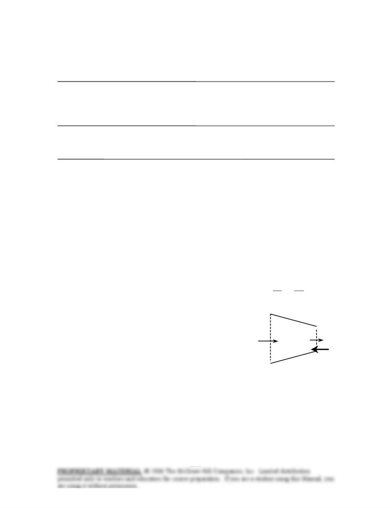
6-17C The force required to hold the plate against the horizontal water stream will increase by a factor of 4
when the velocity is doubled since
2
)( AVVAVVmF
ρρ
=== &
and thus the force is proportional to the square of the velocity.
6-18C The acceleration will not be constant since the force is not constant. The impulse force exerted by
water on the plate is , where V is the relative velocity between the water and
the plate, which is moving. The plate acceleration will be a = F/m. But as the plate begins to move, V
decreases, so the acceleration must also decrease.
2
)( AVVAVVmF
ρρ
=== &
6-19C The maximum velocity possible for the plate is the velocity of the water jet. As long as the plate is
moving slower than the jet, the water will exert a force on the plate, which will cause it to accelerate, until
terminal jet velocity is reached.
6-20 It is to be shown that the force exerted by a liquid jet of velocity V on a stationary nozzle is
proportional to V2, or alternatively, to . √
2
m
&
Assumptions 1 The flow is steady and incompressible. 2 The nozzle is given to be stationary. 3 The nozzle
involves a 90° turn and thus the incoming and outgoing flow streams are normal to each other. 4 The water
is discharged to the atmosphere, and thus the gage pressure at the outlet is zero.
Analysis We take the nozzle as the control volume, and the flow direction at the outlet as the x axis. Note
that the nozzle makes a 90° turn, and thus it does not contribute to any pressure force or momentum flux
term at the inlet in the x direction. Noting that AVm
ρ
=
& where A is the nozzle outlet area and V is the
average nozzle outlet velocity, the momentum equation for steady one-dimensional flow in the x direction
reduces to
∑∑∑ −=
inout
VmVmF
r
&
r
&
r
ββ
→ VmVmF outoutRx &&
β
β
=
=
where FRx is the reaction force on the nozzle due to liquid jet at the nozzle outlet. Then,
AVm
ρ
=
& → or
2
AVAVVVmFRx
βρβρβ
=== &
A
m
A
m
mVmFRx
ρ
β
ρ
ββ
2
&&
&& ===
Therefore, the force exerted by a liquid jet of velocity V on this
stationary nozzle is proportional to V2, or alternatively, to .
2
m
&
N
ozzle
Liquid
F
R
V
Chapter 6 Momentum Analysis of Flow Systems
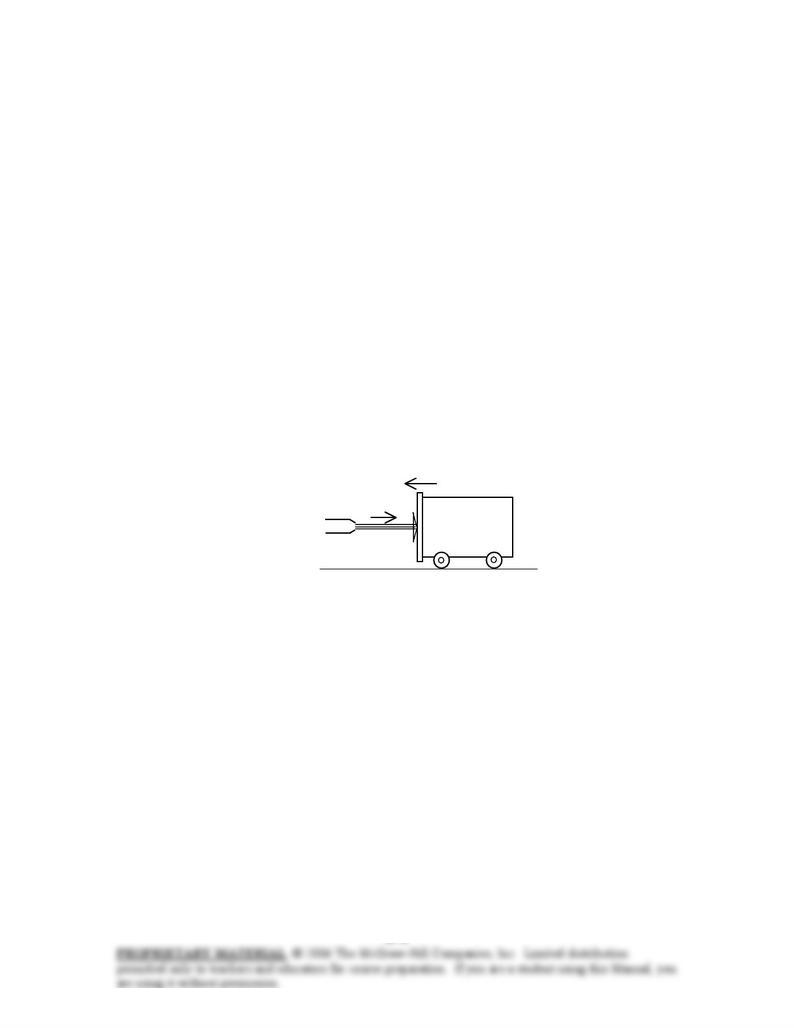
6-21 A water jet of velocity V impinges on a plate moving toward the water jet with velocity ½V. The force
required to move the plate towards the jet is to be determined in terms of F acting on the stationary plate.
Assumptions 1 The flow is steady and incompressible. 2 The plate is vertical and the jet is normal to plate.
3 The pressure on both sides of the plate is atmospheric pressure (and thus its effect cancels out). 4 Fiction
during motion is negligible. 5 There is no acceleration of the plate. 6 The water splashes off the sides of the
plate in a plane normal to the jet. 6 Jet flow is nearly uniform and thus the effect of the momentum-flux
correction factor is negligible,
β
≅ 1.
Analysis We take the plate as the control volume. The relative velocity between the plate and the jet is V
when the plate is stationary, and 1.5V when the plate is moving with a velocity ½V towards the plate.
Then the momentum equation for steady one-dimensional flow in the horizontal direction reduces to
∑ ∑∑ −=
inout
VmVmF
r
&
r
&
r
ββ
→ iiRiiR VmFVmF &&
=
→
−
=
−
Stationary plate: (V AVAVmV iii
ρ
ρ
=
== &
and ) → FAVFR== 2
ρ
Moving plate: (V)5.1(and 5.1 VAAVmV iii
ρ
ρ
=
=
=&) → FAVVAFR25.225.2)5.1( 22 ===
ρρ
Therefore, the force required to hold the plate stationary against the oncoming water jet becomes 2.25
times when the jet velocity becomes 1.5 times.
Discussion Note that when the plate is stationary, V is also the jet velocity. But if the plate moves toward
the stream with velocity ½V, then the relative velocity is 1.5V, and the amount of mass striking the plate
(and falling off its sides) per unit time also increases by 50%.
Waterjet
V
1/2V
Chapter 6 Momentum Analysis of Flow Systems
6-22 A 90° elbow deflects water upwards and discharges it to the atmosphere at a specified rate. The gage
pressure at the inlet of the elbow and the anchoring force needed to hold the elbow in place are to be
determined. √
Assumptions 1 The flow is steady, frictionless, incompressible, and irrotational (so that the Bernoulli
equation is applicable). 2 The weight of the elbow and the water in it is negligible. 3 The water is
discharged to the atmosphere, and thus the gage pressure at the outlet is zero. 4 The momentum-flux
correction factor for each inlet and outlet is given to be
β
= 1.03.
Properties We take the density of water to be 1000 kg/m3.
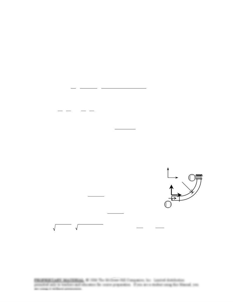
Analysis (a) We take the elbow as the control volume, and designate the entrance by 1 and the outlet by 2.
We also designate the horizontal coordinate by x (with the direction of flow as being the positive direction)
and the vertical coordinate by z. The continuity equation for this one-inlet one-outlet steady flow system is
Noting that kg/s. 30
21 === mmm &&& AVm
ρ
=
&, the mean inlet and outlet velocities of water are
m/s 18.3
]4/m) 1.0()[ kg/m(1000
kg/s25
)4/( 232
21 ======
ππρ
ρ
D
m
A
m
VVV &&
Noting that V1 = V2 and P2 = Patm, the Bernoulli equation for a streamline going through the center of the
reducing elbow is expressed as
()
)(
22 12gage ,112212
2
22
1
2
11 zzgPzzgPPz
g
V
g
P
z
g
V
g
P−=→−=−→++=++
ρρ
ρρ
Substituting,
kPa 3.434==
⋅
=2
2
23
gage ,1 kN/m 434.3
m/skg 1000
kN 1
m) 35.0)(m/s 81.9)(kg/m 1000(P
r
r
r
(b) The momentum equation for steady one-dimensional flow is
∑
∑
∑
−=
inout
VmVmF &&
ββ
. We let the x-
and z- components of the anchoring force of the elbow be FRx and FRz, and assume them to be in the
positive directions. We also use gage pressures to avoid dealing with the atmospheric pressure which acts
on all surfaces. Then the momentum equations along the x and y axes become
VmVmF
VmVmAPF
Rz
Rx
&&
&&
ββ
β
β
=+=
−
=
+−=+
)(
)(0
2
11gage1,
Water
25 kg/s
1
35 cm
F
Rx
F
Rz
2
x
z
Solving for FRx and FRz, and substituting the given values,
N
109
]4/m) 1.0()[N/m 3434(
m/s kg1
N 1
m/s) 8 kg/s)(3.125(03.1 22
2
1gage ,1
−=
−
⋅
−=
−−=
π
β
APVmFRx &
N 9.81
m/s kg1
N 1
m/s) 8 kg/s)(3.125(03.1 2=
⋅
== VmFRy &
β
and °=°−=
−
===+−=+= 143N 136 37
109
9.81
tantan 9.81)109( 1–1–2222
Rx
Ry
RyRxR F
F
FFF
θ
,
Discussion Note that the magnitude of the anchoring force is 136 N, and its line of action makes 143° from
the positive x direction. Also, a negative value for FRx indicates the assumed direction is wrong, and should
be reversed.