Chapter 5 Mass, Bernoulli, and Energy Equations
Energy Equation
5-63C It is impossible for the fluid temperature to decrease during steady, incompressible, adiabatic flow
since this would require the entropy of an adiabatic system to decrease, which would be a violation of the 2nd
law of thermodynamics.
5-64C Yes, the frictional effects are negligible if the fluid temperature remains constant during steady,
incompressible flow since any irreversibility such as friction would cause the entropy and thus temperature of
the fluid to increase during adiabatic flow.
5-65C Head loss is the loss of mechanical energy due to friction in piping expressed as an equivalent column
height of fluid, i.e., head. It is related to the mechanical energy loss in piping by
gm
E
g
e
hL&
&
pipingloss, mech pipingloss, mech == .
5-66C Useful pump head is the useful power input to the pump expressed as an equivalent column height of
fluid. It is related to the useful pumping power input by gm
W
g
w
h&
&
upump, upump,
pump ==
5-67C The kinetic energy correction factor is a correction factor to account for the fact that kinetic energy
using average velocity is not the same as the actual kinetic energy using the actual velocity profile. Its effect
is usually negligible (the square of a sum is not equal to the sum of the squares of its components).
5-68C By Bernoulli Equation, the maximum theoretical height to which the water stream could rise is the
tank water level, which is 20 meters above the ground. Since the water rises above the tank level, the tank
cover must be airtight, containing pressurized air above the water surface. Otherwise, a pump would have to
pressurize the water somewhere in the hose.
Chapter 5 Mass, Bernoulli, and Energy Equations
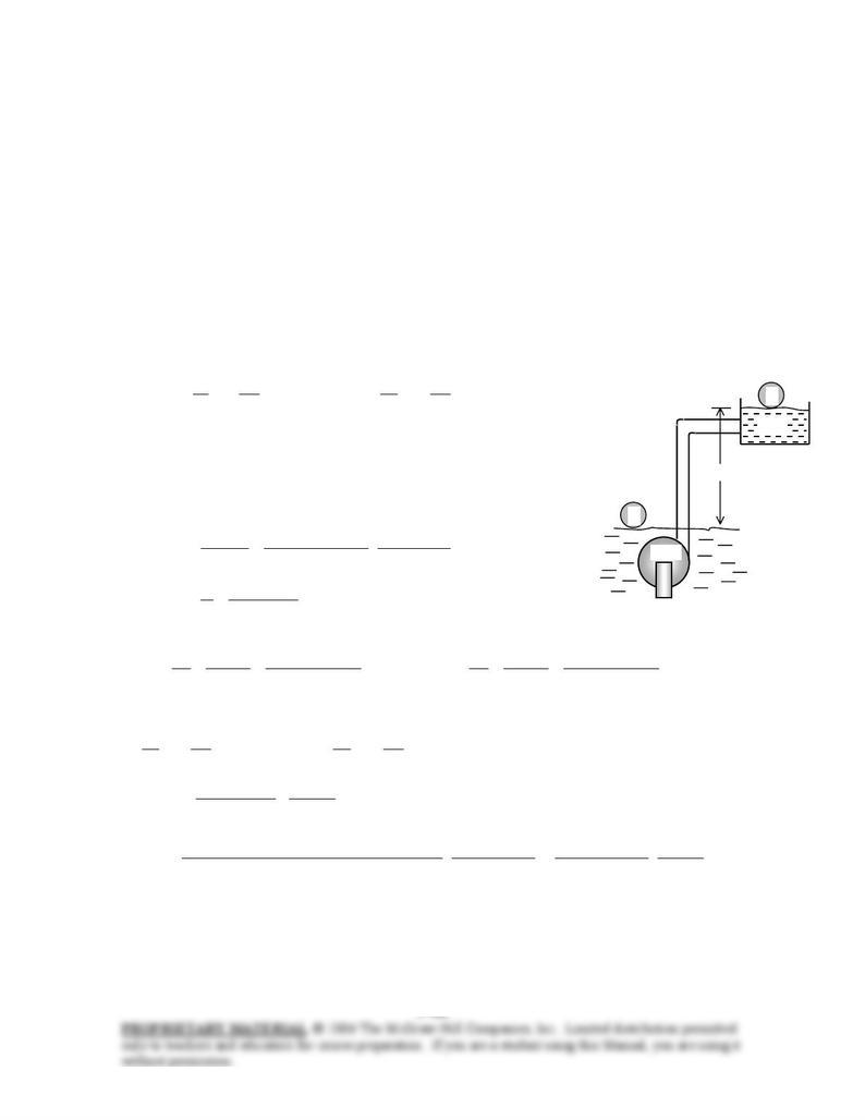
5-69 Underground water is pumped to a pool at a given elevation. The maximum flow rate and the pressures
at the inlet and outlet of the pump are to be determined. √
Assumptions 1 The flow is steady and incompressible. 2 The elevation difference between the inlet and the
outlet of the pump is negligible. 3 We assume the frictional effects in piping to be negligible since the
maximum flow rate is to be determined, 4 The effect of the kinetic energy correction
factors is negligible,
α
= 1.
.0 pippingloss, mech =E
&
Properties We take the density of water to be 1 kg/L = 1000 kg/m3.
Analysis (a) The pump-motor draws 3-kW of power, and is 70% efficient. Then the useful mechanical (shaft)
power it delivers to the fluid is
kW1.2 kW)3)(70.0(
electricmotor–pump upump, === WW &&
η
We take point 1 at the free surface of underground water, which is also taken as the reference level (z1 = 0),
and point 2 at the free surface of the pool. Also, both 1 and 2 are open to the atmosphere (P1 = P2 = Patm), the
velocities are negligible at both points (V1 ≅ V2 ≅ 0), and frictional losses in piping are disregarded. Then the
energy equation for steady incompressible flow through a control volume between these two points that
includes the pump and the pipes reduces to
lossmech,turbine2
2
2
2
2
pump1
2
1
1
1
22 EWgz
VP
mWgz
VP
m&&
&
&
&++
++=+
++
α
ρ
α
ρ
1
2
Pump
Pool
30
m
In the absence of a turbine, and
pipingloss, mech pumploss, mechloss mech, EEE &&& +=
pumploss, mechpump upump, EWW &&& −= . Thus,
W
2 upump, gzm
&
&=
Then the mass and volume flow rates of water become
kg/s14.7
kJ1
/s m 1000
m) )(30m/s (9.81
kJ/s1.2 22
2
2
upump, =
== gz
W
m
&
&
/sm 107.14 33−
×=== 3
kg/m1000
kg/s14.7
ρ
m
&
&
V
(b) We take points 3 and 4 at the inlet and the exit of the pump, respectively, where the flow velocities are
m/s 86.1
4/m) (0.07
/sm 1014.7
4/ 2
33
2
3
3
3=
×
===
−
ππ
D
A
V
VV
&&
, m/s 64.3
4/m) (0.05
/sm 1014.7
4/ 2
33
2
4
4
4=
×
===
−
ππ
D
A
VV
&&
V
We take the pump as the control volume. Noting that z3 = z4, the energy equation for this control volume
reduces to
pumploss, mechturbine4
2
4
4
4
pump3
2
3
3
3
22 EWgz
VP
mWgz
VP
m&&
&
&
&++
++=+
++
α
ρ
α
ρ
→
V
&
&
upump,
2
4
2
3
34 2
)( W
VV
PP +
−
=−
ρα
Substituting,
kPa 289.2=+−=
⋅
×
+
⋅
−
=−
2
33–2
223
34
kN/m)1.2949.4(
kJ1
m kN1
/sm 107.14
kJ/s1.2
m/s kg1000
kN1
2
]m/s) (3.64)m/s 86.1()(1.0)[ kg/m(1000
PP
Discussion In an actual system, the flow rate of water will be less because of friction in pipes. Also, the
effect of flow velocities on the pressure change across the pump is negligible in this case (under 2%) and can
be ignored.
Chapter 5 Mass, Bernoulli, and Energy Equations
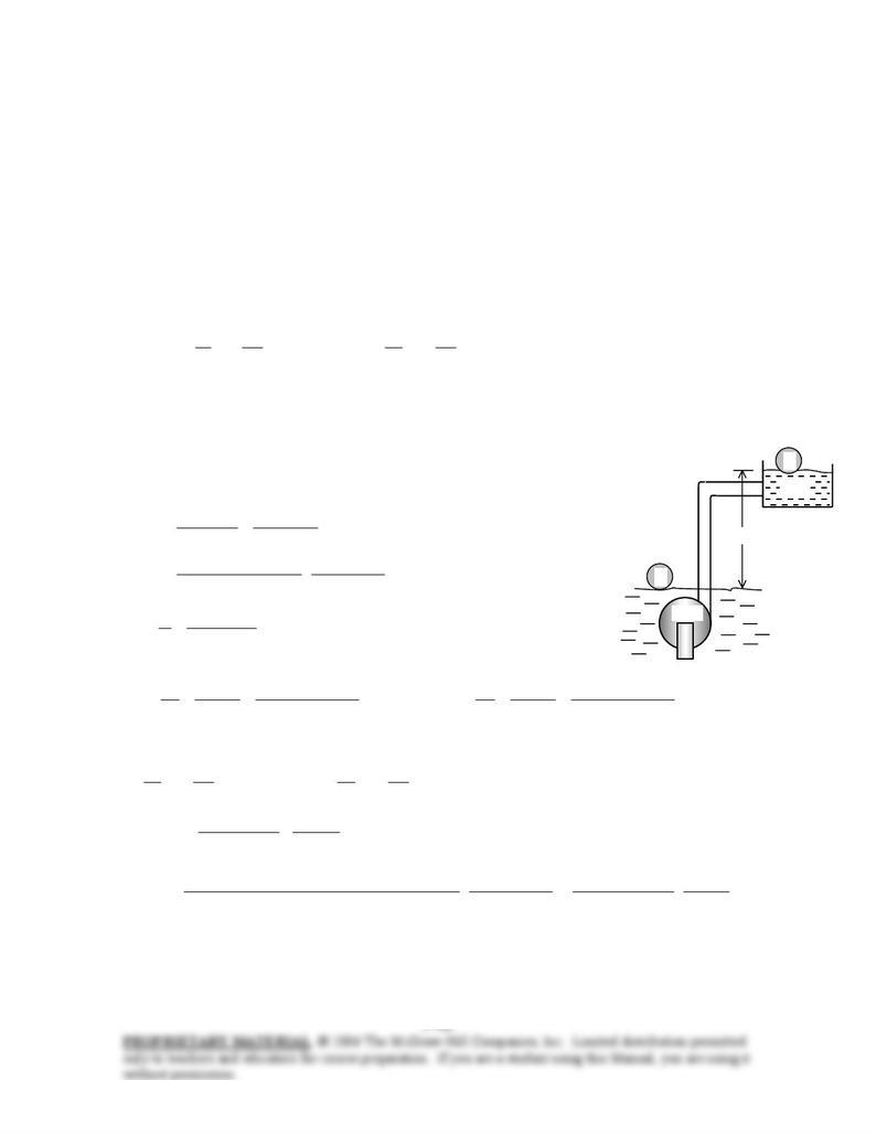
5-70 Underground water is pumped to a pool at a given elevation. For a given head loss, the flow rate and the
pressures at the inlet and outlet of the pump are to be determined. √
Assumptions 1 The flow is steady and incompressible. 2 The elevation difference between the inlet and the
outlet of the pump is negligible. 3 The effect of the kinetic energy correction factors is negligible,
α
= 1.
Properties We take the density of water to be 1 kg/L = 1000 kg/m3.
Analysis (a) The pump-motor draws 3-kW of power, and is 70% efficient. Then the useful mechanical (shaft)
power it delivers to the fluid is
kW1.2 kW)3)(70.0(
electricmotor–pump upump, === WW &&
η
We take point 1 at the free surface of underground water, which is also taken as the reference level (z1 = 0),
and point 2 at the free surface of the pool. Also, both 1 and 2 are open to the atmosphere (P1 = P2 = Patm), and
the velocities are negligible at both points (V1 ≅ V2 ≅ 0). Then the energy equation for steady incompressible
flow through a control volume between these two points that includes the pump and the pipes reduces to
lossmech,turbine2
2
2
2
2
pump1
2
1
1
1
22 EWgz
VP
mWgz
VP
m&&
&
&
&++
++=+
++
α
ρ
α
ρ
In the absence of a turbine, and W
and thus
pipingloss, mech pumploss, mechloss mech, EEE &&& += pumploss, mechpump upump, EW &&& −=
pipingloss, mech2 upump, EgzmW &
&
&+=
Noting that , the mass and volume flow rates of water become
L
ghmE &
&=
loss mech,
kg/s 116.6
kJ 1
/sm 1000
m) 5 )(30m/s (9.81
kJ/s 1.2
)(
22
2
2
u pump,
2
u pump,
=
+
=
+
=
+
=
LL hzg
W
ghgz
W
m
&&
&
/sm 106.12 33−
×≅=== sm
m/116.6
kg/m 1000
kg/s 116.6 3
3
ρ
&
&
V
(b) We take points 3 and 4 at the inlet and the exit of the pump, respectively, where the flow velocities are
2
1
Pump
Pool
30
m
m/s 589.1
4/m) (0.07
/sm 10116.6
4/ 2
33
2
3
3
3=
×
===
−
ππ
D
A
V
VV
&&
, m/s 115.3
4/m) (0.05
/sm 10116.6
4/ 2
33
2
4
4
4=
×
===
−
ππ
D
A
VV
&&
V
We take the pump as the control volume. Noting that z3 = z4, the energy equation for this control volume
reduces to
pumploss, mechturbine4
2
4
4
4
pump3
2
3
3
3
22 EWgz
VP
mWgz
VP
m&&
&
&
&++
++=+
++
α
ρ
α
ρ
→V
2
)( upump,
2
4
2
3
34 &
&
W
VV
PP +
−
=−
ρα
Substituting,
kPa 340≅=+−=
⋅
×
+
⋅
−
=−
kPa
PP
8.339kN/m )4.3436.3(
kJ 1
mkN 1
/sm 106.116
kJ/s 1.2
m/skg 1000
kN 1
2
]m/s) (3.115)m/s 589.1()(1.0)[kg/m (1000
2
33–2
223
34
Discussion Note that frictional losses in pipes causes the flow rate of water to decrease. Also, the effect of
flow velocities on the pressure change across the pump is negligible in this case (about 1%) and can be
ignored.
Chapter 5 Mass, Bernoulli, and Energy Equations
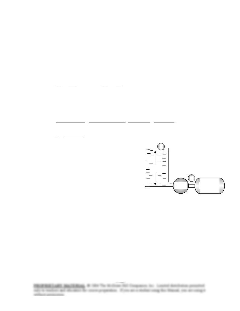
5-71E In a hydroelectric power plant, the elevation difference, the power generation, and the overall turbine-
generator efficiency are given. The minimum flow rate required is to be determined.√
Assumptions 1 The flow is steady and incompressible. 2 The water levels at the reservoir and the discharge
site remain constant. 3 We assume the flow to be frictionless since the minimum flow rate is to be
determined, .0 lossmech, =E
&
Properties We take the density of water to be ρ = 62.4 lbm/ft3.
Analysis We take point 1 at the free surface of the reservoir and point 2 at the free surface of the discharge
water stream, which is also taken as the reference level (z2 = 0). Also, both 1 and 2 are open to the
atmosphere (P1 = P2 = Patm), the velocities are negligible at both points (V1 = V2 = 0), and frictional losses are
disregarded. Then the energy equation in terms of heads for steady incompressible flow through a control
volume between these two points that includes the turbine and the pipes reduces to
1e turbine,e turbine,2
2
2
2
2
upump,1
2
1
1
1
22 zhhhz
g
V
g
P
hz
g
V
g
P
L=→++++=+++
α
ρ
α
ρ
Substituting and noting that W, the extracted turbine head and the mass and
volume flow rates of water are determined to be
e turbine,gen–turbineelect turbine, ghm
&
&
η
=
ft 240
1e turbine, == zh
lbm/s 370=
== kW 1
Btu/s 9478.0
Btu/lbm 1
/sft 037,25
ft) )(240ft/s 0.83(32.2
kW 100 22
2
turbinegen–turbine
electturbine,
gh
W
m
η
&
&
/sft 5.93 3
=== 3
lbm/ft 62.4
lbm/s 370
ρ
m
&
&
V
2
1
Generato
r
Turbine
240 ft
Water
Therefore, the flow rate of water must be at least 5.93 ft3/s to
generate the desired electric power while overcoming friction
losses in pipes.
Discussion In an actual system, the flow rate of water will be
more because of frictional losses in pipes.
Chapter 5 Mass, Bernoulli, and Energy Equations
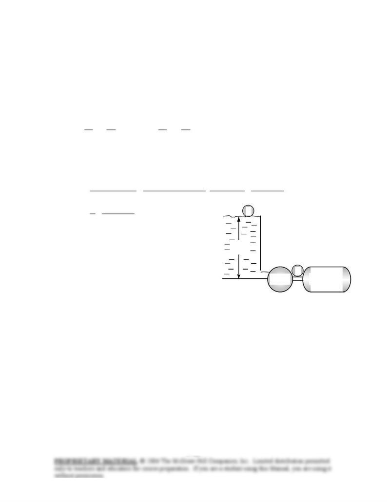
5-72E In a hydroelectric power plant, the elevation difference, the head loss, the power generation, and the
overall turbine-generator efficiency are given. The flow rate required is to be determined. √
Assumptions 1 The flow is steady and incompressible. 2 The water levels at the reservoir and the discharge
site remain constant.
Properties We take the density of water to be ρ = 62.4 lbm/ft3.
Analysis We take point 1 at the free surface of the reservoir and point 2 at the free surface of the discharge
water stream, which is also taken as the reference level (z2 = 0). Also, both 1 and 2 are open to the
atmosphere (P1 = P2 = Patm), the velocities are negligible at both points (V1 = V2 = 0). Then the energy
equation in terms of heads for steady incompressible flow through a control volume between these two points
that includes the turbine and the pipes reduces to
LL hzhhhz
g
V
g
P
hz
g
V
g
P−=→++++=+++ 1e turbine,e turbine,2
2
2
2
2
upump,1
2
1
1
1
22
α
ρ
α
ρ
Substituting and noting that W, the extracted turbine head and the mass and
volume flow rates of water are determined to be
e turbine,gen–turbineelect turbine, ghm
&
&
η
=
ft 20436240
1e turbine, =−=−= L
hzh
lbm/s 435=
== kW1
Btu/s 9478.0
Btu/lbm 1
/sft 037,25
ft) )(204ft/s 0.83(32.2
kW100 22
2
turbinegen–turbine
electturbine,
gh
W
m
η
&
&
/sft 6.98 3
=== 3
lbm/ft 62.4
lbm/s 435
ρ
m
&
&
V
2
1
Generato
r
Turbine
240 ft
Water
Therefore, the flow rate of water must be at least 6.98 ft3/s to
generate the desired electric power while overcoming friction
losses in pipes.
Discussion Note that the effect of frictional losses in pipes is to
increase the required flow rate of water to generate a specified
amount of electric power.