Chapter 13 Open-Channel Flow
Flow Control and Measurement in Channels
13-89C
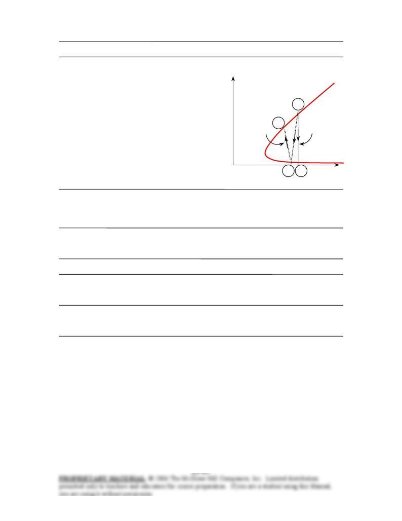
On the figure, diagram 1-2a is for frictionless
gate, 1-2b is for sluice gate with free outflow,
and 1-2b-2c is for sluice gate with drown outflow,
including the hydraulic jump back to subcritical flow.
.
13-90C For sluice gates, the discharge coefficient Cd is defined as the ratio of the actual velocity through
the gate to the maximum velocity as determined by the Bernoulli equation for the idealized frictionless
flow case, for which Cd = 1. Typical values of Cd for sluice gates with free outflow are in the range of
0.55 to 0.60.
13-91C The operation of broad crested weir is based on blocking the flow in the channel with a large
rectangular block, and establishing critical flow over the block. Then the flow rate can be determined by
measuring flow depths.
13-92C In the case of subcritical flow, the flow depth y will decrease during flow over the bump.
13-93C When the specific energy reaches its minimum value, the flow is critical, and the flow at this point
is said to be choked. If the bumper height is increased even further, the flow remains critical and thus
choked. The flow will not become supercritical.
13-94C A sharp-crested weir is a vertical plate placed in a channel that forces the fluid to flow through an
opening to measure the flow rate. They are characterized by the shape of the opening. For example, a weir
with a triangular opening is referred to as a triangular weir.
y
E
s1 = Es2a
(c) Drown
outflow
(a) Frictionless
gate
•
2c
2b
•
1
•
2a
•
Supercritical
flow
Subcritical
flow
E
s
Chapter 13 Open-Channel Flow
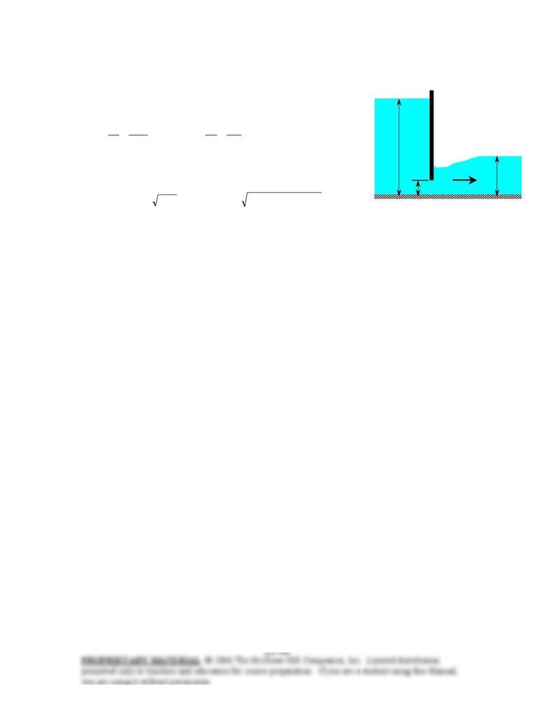
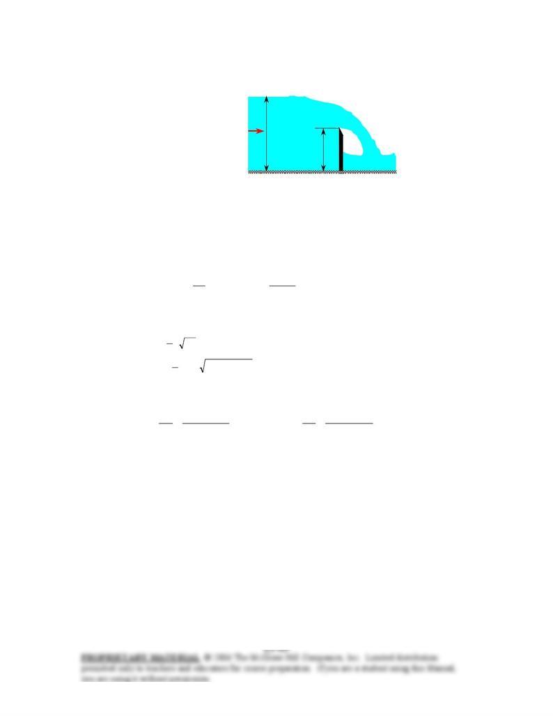
13-95 Water is released from a reservoir through a sluice gate into an open channel. For specified flow
depths, the rate of discharge is to be determined. √EES
Assumptions 1 The flow is steady or quasi-steady. 2 The channel
is sufficiently wide so that the end effects are negligible.
Analysis The depth ratio y1/a and the contraction coefficient y2/a are
14
m 1
m 14
1==
a
y and 3
m 1
m 3
2==
a
y
The corresponding discharge coefficient is determined from Fig.
13-38 to be Cd = 0.59. Then the discharge rate becomes
/sm 48.9 3
=== m) 14)(m/s (9.812m) m)(1 5(59.02 2
1
gybaCd
V
&
a = 1
m
y2 = 3 m
Sluice gate
y1 = 14 m
Discussion Discharge coefficient is the same as free flow because of small depth ratio after the gate. So,
the flow rate would not change if it were not drowned.
Chapter 13 Open-Channel Flow
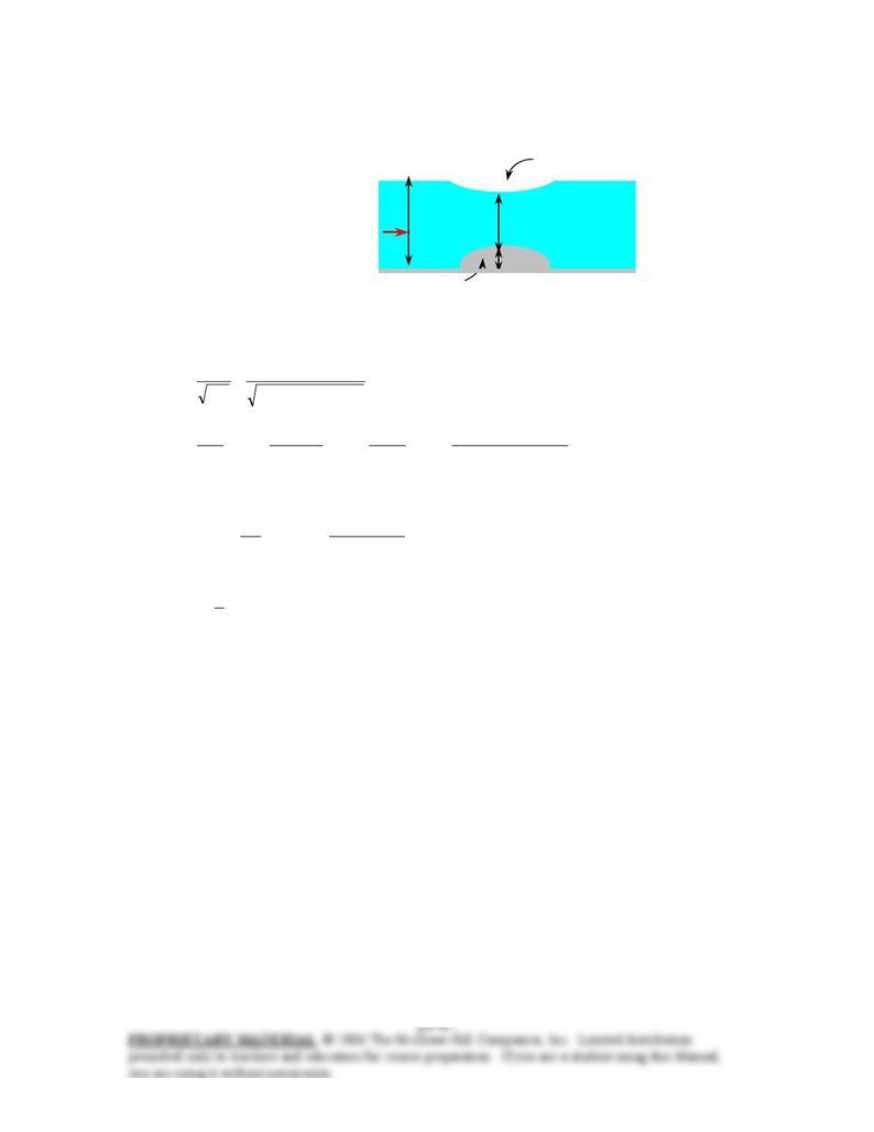
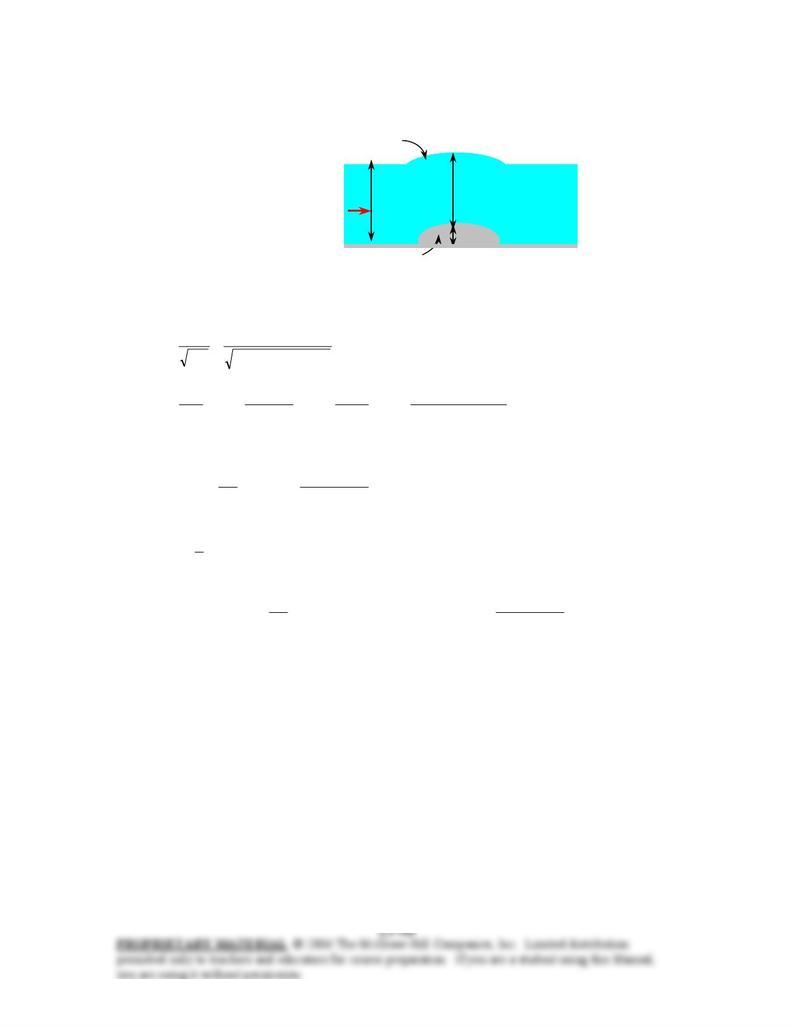
13-96 Water flowing in a horizontal open channel encounters a bump. It will be determined if the flow
over the bump is choked. √EES
Depression over the bump
Assumptions 1 The flow is steady. 2 Frictional effects are negligible so that there is no dissipation of
mechanical energy. 3 The channel is sufficiently wide so that the end effects are negligible.
y
2
y
2
y
1=0.80 m
y
1=1.2 m
V 1 =1.2 m/s
V1 =2.5 m/s
Bump Bump
∆
z
= 0.15
m
∆
z
b=0.22
m
Analysis The upstream Froude number and the critical depth are
729.0
m) /s)(1.2m (9.81
m/s 5.2
Fr
2
1
1
1===
gy
V
m 972.0
m/s 9.81
s)/m 5.2(m) 2.1(
)( 3/1
2
22
3/1
2
1
2
1
3/1
2
2
11
3/1
2
2
=
=
=
=
=g
Vy
gb
Vby
gb
yc
V
&
The flow is subcritical since Fr < 1, and the flow depth decreases over the bump. The upstream, over the
bump, and critical specific energy is
m 52.1
)m/s 2(9.81
m/s) 5.2(
m) 2.1(
22
2
2
1
11 =+=+= g
V
yEs
m1.300.221.52
12
=
−=∆−= b
ss zEE
m1.46
2
3== cc yE
We have an interesting situation: The calculations show that Es2 < Ec. That is, the specific energy of the
fluid decreases below the level of energy at the critical point, which is the minimum energy, and this is
impossible. Therefore, the flow at specified conditions cannot exist. The flow is choked when the specific
energy drops to the minimum value of 1.46 m, which occurs at a bump-height of
. m06.046.11.52
1
max, =−=−=∆ cs
bEEz
Discussion A bump-height over 6 cm results in a reduction in the flow rate of water, or a rise of upstream
water level. Therefore, a 22-cm high bump alters the upstream flow. On the other hand, a bump less than 6
cm high will not affect the upstream flow.
Chapter 13 Open-Channel Flow
13-97 Water flowing in a horizontal open channel encounters a bump. The change in the surface level over
the bump and the type of flow (sub- or supercritical) over the bump are to be determined. √EES
Rise over the bump
Assumptions 1 The flow is steady. 2 Frictional effects are negligible so that there is no dissipation of
mechanical energy. 3 The channel is sufficiently wide so that the end effects are negligible.
y
2
y
2
y
1=0.80 m
y
1= 0.8 m
V
1 =1.2 m/s
V1 = 8 m/s
Bump Bump
∆
z
= 0.15
m
∆
z
b=0.30
m
Analysis The upstream Froude number and the critical depth are
856.2
m) /s)(0.8m (9.81
m/s 8
Fr
2
1
1
1===
gy
V
m 61.1
m/s 9.81
s)/m 8(m) 8.0(
)( 3/1
2
22
3/1
2
1
2
1
3/1
2
2
11
3/1
2
2
=
=
=
=
=g
Vy
gb
Vby
gb
yc
V
&
The upstream flow is supercritical since Fr > 1, and the flow depth increases over the bump. The upstream,
over the bump, and critical specific energy are
m 06.4
)m/s 2(9.81
m/s) 8(
m) 8.0(
22
2
2
1
11 =+=+= g
V
yEs
m3.760.304.06
12
=
−=∆−= b
ss zEE
m42.2
2
3== cc yE
The flow depth over the bump can be determined from
0
2
)( 2
1
2
1
2
21
3
2=+∆−− y
g
V
yzEy b
s → 0m) 80.0(
)m/s 2(9.81
m/s) 8(
)m 30.006.4( 2
2
2
2
2
3
2=+−− yy
Using an equation solver, the physically meaningful root of this equation is determined to be 0.846 m.
Therefore, there is a rise of
m 0.346
=
+
−
=
∆+−= 30.080.0846.0over bump Rise 12 b
zyy
over the surface relative to the upstream water surface. The specific energy decreases over the bump from,
4.06 to 3.76 m, but it is still over the minimum value of 2.42 m. Therefore, the flow over the bump is still
supercritical.
Discussion The actual value of surface rise may be different than the 4.6 cm because of the frictional
effects that are neglected in the analysis.
Chapter 13 Open-Channel Flow
13-98 The flow rate in an open channel is to be measured using a sharp-crested rectangular weir. For a
measured value of flow depth upstream, the flow rate is to be determined. √EES
V1
y
1 = 2.2 m
P
w = 0.75 m
Sharp-crested
rectangular weir
Assumptions 1 The flow is steady. 2 The upstream velocity head is negligible. 3 The channel is sufficiently
wide so that the end effects are negligible.
Analysis The weir head is
m 45.175.02.2
1=−=−= w
PyH
The discharge coefficient of the weir is
771.0
m 75.0
m 45.1
0897.0598.00897.0598.0
rec, =+=+=
w
wd P
H
C
The condition H/Pw < 2 is satisfied since 1.45/0.75 = 1.93. Then the water flow rate through the channel
becomes
/sm 15.9 3
=
=
=
2/32
2/3
rec,
rec
)m 45.1()m/s 2(9.81m) 4(
3
2
)7714.0(
2
3
2HgbC wd
V
&
Discussion The upstream velocity and the upstream velocity head are
m/s 81.1
m) m)(2.2 (4
/sm 9.15 3
1
1=== by
V
V
&
and m 167.0
)m/s 2(9.81
m/s) 81.1(
22
2
2
1==
g
V
This is 11.5% of the weir head, which is significant. When the upstream velocity head is considered, the
flow rate becomes 18.1 m3/s, which is about 14 percent higher than the value determined above. Therefore,
it is good practice to consider the upstream velocity head unless the weir height Pw is very large relative to
the weir head H.