Chapter 11 Flow Over Bodies: Drag and Lift
Chapter 11
FLOW OVER BODIES: DRAG AND LIFT
Drag, Lift, and Drag Coefficients of Common Geometries
11-1C The flow over a body is said to be two-dimensional when the body is too long and of constant cross-
section, and the flow is normal to the body (such as the wind blowing over a long pipe perpendicular to its
axis). There is no significant flow along the axis of the body. The flow along a body that possesses
symmetry along an axis in the flow direction is said to be axisymmetric (such as a bullet piercing through
air). Flow over a body that cannot be modeled as two-dimensional or axisymmetric is three-dimensional.
The flow over a car is three-dimensional.
11-2C The velocity of the fluid relative to the immersed solid body sufficiently far away from a body is
called the free-stream velocity, V. The upstream (or approach) velocity V is the velocity of the approaching
fluid far ahead of the body. These two velocities are equal if the flow is uniform and the body is small
relative to the scale of the free-stream flow.
11-3C A body is said to be streamlined if a conscious effort is made to align its shape with the anticipated
streamlines in the flow. Otherwise, a body tends to block the flow, and is said to be blunt. A tennis ball is a
blunt body (unless the velocity is very low and we have “creeping flow”).
11-4C Some applications in which a large drag is desirable: Parachuting, sailing, and the transport of
pollens.
11-5C The force a flowing fluid exerts on a body in the flow direction is called drag. Drag is caused by
friction between the fluid and the solid surface, and the pressure difference between the front and back of
the body. We try to minimize drag in order to reduce fuel consumption in vehicles, improve safety and
durability of structures subjected to high winds, and to reduce noise and vibration.
11-6C The force a flowing fluid exerts on a body in the normal direction to flow that tend to move the body
in that direction is called lift. It is caused by the components of the pressure and wall shear forces in the
normal direction to flow. The wall shear also contributes to lift (unless the body is very slim), but its
contribution is usually small.
11-7C When the drag force FD, the upstream velocity V, and the fluid density ρ are measured during flow
over a body, the drag coefficient can be determined from
AV
F
CD
D2
2
1
ρ
=
where A is ordinarily the frontal area (the area projected on a plane normal to the direction of flow) of the
body.

Chapter 11 Flow Over Bodies: Drag and Lift
11-8C When the lift force FL, the upstream velocity V, and the fluid density ρ are measured during flow
over a body, the lift coefficient can be determined from
AV
F
CL
L2
2
1
ρ
=
where A is ordinarily the planform area, which is the area that would be seen by a person looking at the
body from above in a direction normal to the body.
11-9C The frontal area of a body is the area seen by a person when looking from upstream. The frontal
area is appropriate to use in drag and lift calculations for blunt bodies such as cars, cylinders, and spheres.
11-10C The planform area of a body is the area that would be seen by a person looking at the body from
above in a direction normal to flow. The planform area is appropriate to use in drag and lift calculations for
slender bodies such as flat plate and airfoils when the frontal area is very small.
11-11C The maximum velocity a free falling body can attain is called the terminal velocity. It is determined
by setting the weight of the body equal to the drag and buoyancy forces, W = FD + FB.
11-12C The part of drag that is due directly to wall shear stress τw is called the skin friction drag FD, friction
since it is caused by frictional effects, and the part that is due directly to pressure P and depends strongly
on the shape of the body is called the pressure drag FD, pressure. For slender bodies such as airfoils, the
friction drag is usually more significant.
11-13C The friction drag coefficient is independent of surface roughness in laminar flow, but is a strong
function of surface roughness in turbulent flow due to surface roughness elements protruding further into
the highly viscous laminar sublayer.
11-14C (a) In general, the drag coefficient decreases with the Reynolds number at low and moderate
Reynolds numbers. (b) The drag coefficient is nearly independent of the Reynolds number at high
Reynolds numbers (Re > 104).
11-15C As a result of attaching fairings to the front and back of a cylindrical body at high Reynolds
numbers, (a) friction drag increases, (b) pressure drag decreases, and (c) total drag decreases.
11-16C As a result of streamlining, (a) friction drag increases, (b) pressure drag decreases, and (c) total
drag decreases at high Reynolds numbers (the general case), but increases at very low Reynolds numbers
since the friction drag dominates at low Reynolds numbers.
11-17C At sufficiently high velocities, the fluid stream detaches itself from the surface of the body. This is
called separation. It is caused by a fluid flowing over a curved surface at a high velocity (or technically, by
adverse pressure gradient). Separation increases the drag coefficient drastically.
11-18C For a moving body to follow another moving body closely by staying close behind is called
drafting. It reduces the pressure drag and thus the drag coefficient for the drafted body by taking advantage
of the low pressure wake region of the moving body in front.
11-19C The car that is contoured to resemble an ellipse has a smaller drag coefficient and thus smaller air
resistance, and it is more likely to be more fuel efficient than a car with sharp corners.
11-20C The bicyclist who leans down and brings his body closer to his knees will go faster since the frontal
area and thus the drag force will be less in that position. The drag coefficient will also go down somewhat,
but this is a secondary effect.
Chapter 11 Flow Over Bodies: Drag and Lift
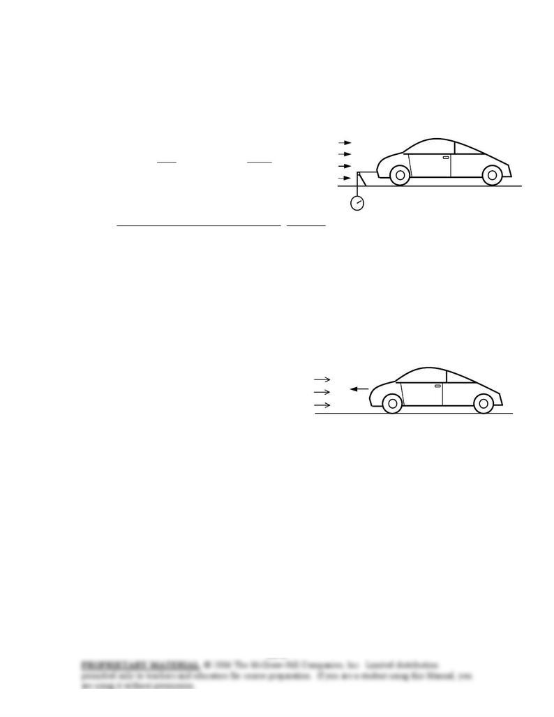
11-21 The drag force acting on a car is measured in a wind tunnel. The drag coefficient of the car at the test
conditions is to be determined. √
Assumptions 1 The flow of air is steady and incompressible. 2 The cross-section of the tunnel is large
enough to simulate free flow over the car. 3 The bottom of the tunnel is also moving at the speed of air to
approximate actual driving conditions or this effect is negligible. 4 Air is an ideal gas.
Properties The density of air at 1 atm and 25°C is ρ = 1.164 kg/m3.
Analysis The drag force acting on a body and the drag coefficient
are given by
FD
Wind tunnel
90 km/h
2
22
and
2AV
F
C
V
ACF D
DDD
ρ
ρ
==
where A is the frontal area. Substituting and noting that 1 m/s =
3.6 km/h, the drag coefficient of the car is determined to be
0.42=
⋅
×
×
=N 1
m/s kg1
m/s) 6.3/90)(m 65.140.1)( kg/m164.1(
N) 350(2 2
223
D
C
Discussion Note that the drag coefficient depends on the design conditions, and its value will be different
at different conditions. Therefore, the published drag coefficients of different vehicles can be compared
meaningfully only if they are determined under identical conditions. This shows the importance of
developing standard testing procedures in industry.
11-22 A car is moving at a constant velocity. The upstream velocity to be used in fluid flow analysis is to
be determined for the cases of calm air, wind blowing against the direction of motion of the car, and wind
blowing in the same direction of motion of the car. √
Analysis In fluid flow analysis, the velocity used is the relative
velocity between the fluid and the solid body. Therefore:
80 km/h
Wind
(a) Calm air: V = Vcar = 80 km/h
(b) Wind blowing against the direction of motion:
V = Vcar + Vwind = 80 + 30 = 110 km/h
(c) Wind blowing in the same direction of motion:
V = Vcar – Vwind = 80 – 50 = 30 km/h
Discussion Note that the wind and car velocities are added when they are in opposite directions, and
subtracted when they are in the same direction.
Chapter 11 Flow Over Bodies: Drag and Lift
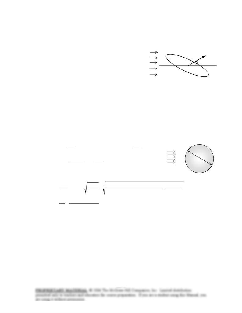
11-23 The resultant of the pressure and wall shear forces acting on a body is given. The drag and the lift
forces acting on the body are to be determined.
Analysis The drag and lift forces are determined by decomposing the resultant force into its components in
the flow direction and the normal direction to flow,
Drag force: N 573
=
°== 35cos)N 700(cos
θ
RD FF
V
35°
FR=700 N
Lift force: N 402
=
°== 35sin)N 700(sin
θ
RL FF
Discussion Note that the greater the angle between the resultant
force and the flow direction, the greater the lift.
11-24 The total drag force acting on a spherical body is measured, and the pressure drag acting on the body
is calculated by integrating the pressure distribution. The friction drag coefficient is to be determined.
Assumptions 1 The flow of air is steady and incompressible. 2 The surface of the sphere is smooth. 3 The
flow over the sphere is turbulent (to be verified).
Properties The density and kinematic viscosity of air at 1 atm and 5°C are ρ = 1.269 kg/m3 and ν =
1.382×10⁻⁵ m
2/s. The drag coefficient of sphere in turbulent flow is CD = 0.2, and its frontal area is A =
πD2/4 (Table 11-2).
Analysis The total drag force is the sum of the friction and pressure drag forces. Therefore,
N 3.09.42.5
pressure,friction, =−=−= DDD FFF
where
2
and
2
2
friction,friction,
2V
ACF
V
ACF DDDD
ρρ
==
Air
V
D
= 12 cm
Taking the ratio of the two relations above gives
0.0115=== (0.2)
N 5.2
N 0.3
friction,
friction, D
D
D
DC
F
F
C
Now we need to verify that the flow is turbulent. This is done by calculating
the flow velocity from the drag force relation, and then the Reynolds number:
m/s 2.60
N 1
m/skg 1
]4/m) 12.0()[2.0)(kg/m (1.269
N) 2.5(2
2
2
2
23
2
=
⋅
==→=
π
ρ
ρ
AC
F
V
V
ACF
D
D
DD
5
25– 1023.5
/m 101.382
m) m/s)(0.12 (60.2
Re ×=
×
==
s
VD
ν
which is greater than 2×10⁵. Therefore, the flow is turbulent as assumed.
Discussion Note that knowing the flow regime is important in the solution of this problem since the total
drag coefficient for a sphere is 0.5 in laminar flow and 0.2 in turbulent flow.
Chapter 11 Flow Over Bodies: Drag and Lift
11-25E The frontal area of a car is reduced by redesigning. The amount of fuel and money saved per year
as a result are to be determined. √EES
Assumptions 1 The car is driven 12,000 miles a year at an average speed of 55 km/h. 2 The effect of
reduction of the frontal area on the drag coefficient is negligible.
Properties The densities of air and gasoline are given to be 0.075 lbm/ft3 and 50 lbm/ft3, respectively. The
heating value of gasoline is given to be 20,000 Btu/lbm. The drag coefficient is CD = 0.3 for a passenger car
(Table 11-2).
Analysis The drag force acting on a body is determined from
2
2
V
ACF DD
ρ
=
where A is the frontal area of the body. The drag force acting on the car before redesigning is
lbf 9.40
ft/slbm 32.2
lbf 1
mph 1
ft/s 1.4667
2
mph) 55)(lbm/ft 075.0(
)ft 18(3.0 2
2
23
2=
⋅
=
D
F
Noting that work is force times distance, the amount of work done to overcome this drag force and the
required energy input for a distance of 12,000 miles are
Btu/year 10041.1
32.0
Btu/year 1033.3
Btu/year 1033.3
ftlbf 169.778
Btu 1
mile 1
ft 5280
)miles/year 0lbf)(12,00 9.40(
7
6
car
drag
6
drag
×=
×
==
×=
⋅
==
η
W
E
LFW
in
D
Then the amount and costs of the fuel that supplies this much energy are
/yearft 41.10
lbm/ft 50
Btu/lbm) 000,20/()Btu/year 10041.1(
/HV
fuel ofAmont 3
3
7
fuel
in
fuel
fuel =
×
===
ρρ
E
m
r$171.3/yea
ft 1
gal 7.4804
20/gal)/year)($2.ft (10.41cost) fuel)(Unit of(Amount Cost 3
3=
==
That is, the car uses 10.41 ft3 = 77.9 gallons of gasoline at a cost of $171.3 per year to overcome the drag.
The drag force and the work done to overcome it are directly proportional to the frontal area. Then
the percent reduction in the fuel consumption due to reducing frontal area is equal to the percent reduction
in the frontal area:
$28.6/year
gal/year 13.0
===
==
=
=
−
=
−
=
ar)($171.3/ye167.0Cost)(ratio) (ReductionreductionCost
gal/year) (77.9167.0
Amount)(ratio) (ReductionreductionAmount
167.0
18
1518
ratioReduction new
A
AA
Therefore, reducing the frontal area reduces the fuel consumption due to drag by 16.7%.
Discussion Note from this example that significant reductions in drag and fuel consumption can be
achieved by reducing the frontal area of a vehicle.