Chapter 11 Flow Over Bodies: Drag and Lift
Lift
11-71C The contribution of viscous effects to lift is usually negligible for airfoils since the wall shear is
parallel to the surfaces of such devices and thus nearly normal to the direction of lift.
11-72C When air flows past a symmetrical airfoil at zero angle of attack, (a) the lift will be zero, but (b) the
drag acting on the airfoil will be nonzero.
11-73C When air flows past a nonsymmetrical airfoil at zero angle of attack, both the (a) lift and (b) drag
acting on the airfoil will be nonzero.
11-74C When air flows past a symmetrical airfoil at an angle of attack of 5°, both the (a) lift and (b) drag
acting on the airfoil will be nonzero.
11-75C The decrease of lift with an increase in the angle of attack is called stall. When the flow separates
over nearly the entire upper half of the airfoil, the lift is reduced dramatically (the separation point is near
the leading edge). Stall is caused by flow separation and the formation of a wide wake region over the top
surface of the airfoil. The commercial aircraft are not allowed to fly at velocities near the stall velocity for
safety reasons. Airfoils stall at high angles of attack (flow cannot negotiate the curve around the leading
edge). If a plane stalls, it loses mush of its lift, and it can crash.
11-76C Both the lift and the drag of an airfoil increase with an increase in the angle of attack, but in
general lift increases at a much higher rate than does the drag.
11-77C Flaps are used at the leading and trailing edges of the wings of large aircraft during takeoff and
landing to alter the shape of the wings to maximize lift and to enable the aircraft to land or takeoff at low
speeds. An aircraft can takeoff or land without flaps, but it can do so at very high velocities, which is
undesirable during takeoff and landing.
11-78C Flaps increase both the lift and the drag of the wings. But the increase in drag during takeoff and
landing is not much of a concern because of the relatively short time periods involved. This is the penalty
we pay willingly to takeoff and land at safe speeds.
11-79C The effect of wing tip vortices is to increase drag (induced drag) and to decrease lift. This effect is
also due to the downwash, which causes an effectively smaller angle of attack.
11-80C Induced drag is the additional drag caused by the tip vortices. The tip vortices have a lot of kinetic
energy, all of which is wasted and is ultimately dissipated as heat in the air downstream. The induced drag
can be reduced by using long and narrow wings.
11-81C When air is flowing past a spherical ball, the lift exerted on the ball will be zero if the ball is not
spinning, and it will be nonzero if the ball is spinning about an axis normal to the free stream velocity (no
lift will be generated if the ball is spinning about an axis parallel to the free stream velocity).
Chapter 11 Flow Over Bodies: Drag and Lift
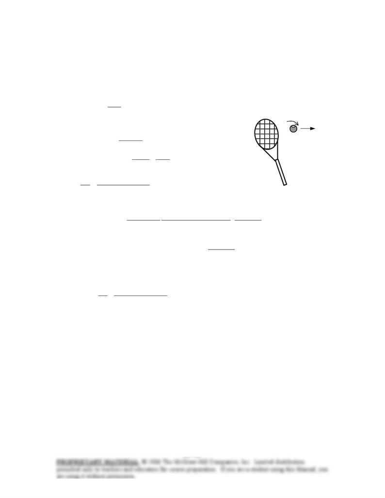
11-82 A tennis ball is hit with a backspin. It is to be determined if the ball will fall or rise after being hit.
Assumptions 1 The outer surface of the ball is smooth enough for Fig. 11-53 to be applicable. 2 The ball is
hit horizontally so that it starts its motion horizontally.
Properties The density and kinematic viscosity of air at 1 atm and 25°C are ρ = 1.184 kg/m3 and ν =
1.562×10⁻⁵ m2/s.
Analysis The ball is hit horizontally, and thus it would normally fall under the effect of gravity without the
spin. The backspin will generate a lift, and the ball will rise if the lift is greater than the weight of the ball.
The lift can be determined from
2
2
V
ACF LL
ρ
=
where A is the frontal area of the ball, which is . The
regular and angular velocities of the ball are
4/
2
DA
π
=4200 rpm
m/s 56.25
km/h3.6
m/s 1
km/h)92( =
=V 92 km/h
rad/s 440
s 60
min 1
rev 1
rad 2
rev/min) 4200( =
=
π
ω
Then,
rad551.0
m/s) 56.25(2
m) 064 rad/s)(0.440(
2==
V
D
ω
From Fig. 11-53, the lift coefficient corresponding to this value is CL = 0.11. Then the lift acting on the ball
is
N 14.0
m/skg 1
N 1
2
m/s) 56.25)(kg/m 184.1(
4
m) 064.0(
)11.0( 2
232
=
⋅
=
π
L
F
The weight of the ball is
N 56.0
m/skg 1
N 1
)m/s 81.9)(kg 057.0( 2
2=
⋅
== mgW
which is more than the lift. Therefore, the ball will drop under the combined effect of gravity and lift due
to spinning after hitting, with a net force of 0.56 – 0.14 = 0.42 N.
Discussion The Reynolds number for this problem is
5
25 1005.1
/sm 10562.1
m) .0645.56m/s)(02(
Re ×=
×
== −
υ
VD
L
which is close enough to 6×10⁴ for which Fig. 11-53 is prepared. Therefore, the result should be close
enough to the actual answer.
Chapter 11 Flow Over Bodies: Drag and Lift
11-83 The takeoff speed of an aircraft when it is fully loaded is given. The required takeoff speed when the
weight of the aircraft is increased by 20% as a result of overloading is to be determined. √
Assumptions 1 The atmospheric conditions (and thus the properties of air) remain the same. 2 The settings
of the plane during takeoff are maintained the same so that the lift coefficient of the plane remains the
same.
Analysis An aircraft will takeoff when lift equals the total weight. Therefore,
AC
W
VAVCWFW
L
LL
ρ
ρ
2
2
2
1=→=→= Takeoff
V = 190 km/h
We note that the takeoff velocity is proportional to the square root
of the weight of the aircraft. When the density, lift coefficient, and
area remain constant, the ratio of the velocities of the overloaded
and fully loaded aircraft becomes
1
2
12
1
2
1
2
1
2
/2
/2
W
W
VV
W
W
ACW
ACW
V
V
L
L=→==
ρ
ρ
Substituting, the takeoff velocity of the overloaded aircraft is determined to be
km/h 208=== 1.2km/h) 190(
2.1
1
1
12 W
W
VV
Discussion A similar analysis can be performed for the effect of the variations in density, lift coefficient,
and planform area on the takeoff velocity.
Chapter 11 Flow Over Bodies: Drag and Lift
11-84 The takeoff speed and takeoff time of an aircraft at sea level are given. The required takeoff speed,
takeoff time, and the additional runway length required at a higher elevation are to be determined.
Assumptions 1 Standard atmospheric conditions exist. 2 The settings of the plane during takeoff are
maintained the same so that the lift coefficient of the plane and the planform area remain constant. 3 The
acceleration of the aircraft during takeoff remains constant.
Properties The density of standard air is ρ1 = 1.225 kg/m3 at sea level, and ρ2 = 1.048 kg/m3 at 1600 m
altitude.
Analysis (a) An aircraft will takeoff when lift equals the total weight. Therefore,
AC
W
VAVCWFW
L
LL
ρ
ρ
2
2
2
1=→=→=
We note that the takeoff speed is inversely proportional to the square root of air density. When the weight,
lift coefficient, and area remain constant, the ratio of the speeds of the aircraft at high altitude and at sea
level becomes
km/h 238===→== 048.1
225.1
km/h) 220(
/2
/2
2
1
12
2
1
1
2
1
2
ρ
ρ
ρ
ρ
ρ
ρ
VV
ACW
ACW
V
V
L
L
Therefore, the takeoff velocity of the aircraft at higher altitude is 238 km/h.
(b) The acceleration of the aircraft at sea level is
2
m/s 074.4
km/h3.6
m/s 1
s 15
0 – km/h220 =
=
∆
∆
=t
V
a Takeoff
V = 220 km/h
which is assumed to be constant both at sea level and the higher
altitude. Then the takeoff time at the higher altitude becomes
s 16.2=
=
∆
=∆→
∆
∆
=km/h 3.6
m/s 1
m/s 4.074
0 –km/h 238
2
a
V
t
t
V
a
(c) The additional runway length is determined by calculating the distance
traveled during takeoff for both cases, and taking their difference:
m 458s) 15)(m/s 074.4( 22
2
1
2
1
2
1
1=== atL
m 535s) 2.16)(m/s 074.4( 22
2
1
2
2
2
1
2=== atL
m 77=−=−=∆ 458535
12 LLL
Discussion Note that altitude has a significant effect on the length of the runways, and it should be a major
consideration on the design of airports. It is interesting that a 1.2 second increase in takeoff time increases
the required runway length by about 100 m.
Chapter 11 Flow Over Bodies: Drag and Lift
11-85E The rate of fuel consumption of an aircraft while flying at a low altitude is given. The rate of fuel
consumption at a higher altitude is to be determined for the same flight velocity.
Assumptions 1 Standard atmospheric conditions exist. 2 The settings of the plane during takeoff are
maintained the same so that the drag coefficient of the plane and the planform area remain constant. 3 The
velocity of the aircraft and the propulsive efficiency remain constant. 4 The fuel is used primarily to
provide propulsive power to overcome drag, and thus the energy consumed by auxiliary equipment (lights,
etc) is negligible.
Properties The density of standard air is ρ1 = 0.05648 lbm/ft3 at 10,000 ft, and ρ2 = 0.02866 lbm/ft3 at
30,000 ft altitude.
Analysis When an aircraft cruises steadily (zero acceleration) at a constant altitude, the net force acting on
the aircraft is zero, and thus the thrust provided by the engines must be equal to the drag force. Also, power
is force times velocity (distance per unit time), and thus the propulsive power required to overcome drag is
equal to the thrust times the cruising velocity. Therefore, Cruising
mfuel = 5 gal/min
22
Thrust
32
propulsive
V
ACV
V
ACVFVW DDD
ρρ
===×=
&
The propulsive power is also equal to the product of the rate of fuel energy
supplied (which is the rate of fuel consumption times the heating value of
the fuel, ) and the propulsive efficiency. Then, HV
fuel
m
&
HV
2
HV fuelprop
3
fuelpropprop m
V
ACmW D&&
&
η
ρ
η
=→=
We note that the rate of fuel consumption is proportional to the density of air. When the drag coefficient,
the wing area, the velocity, and the propulsive efficiency remain constant, the ratio of the rates of fuel
consumptions of the aircraft at high and low altitudes becomes
gal/min 2.54===→== 0.05648
0.02866
gal/min) 5(
HV 2/
HV 2/
1
2
1 fuel,2 fuel,
1
2
prop
3
1
prop
3
2
1 fuel,
2 fuel,
ρ
ρ
ρ
ρ
ηρ
ηρ
mm
VAC
VAC
m
m
D
D&&
&
&
Discussion Note the fuel consumption drops by half when the aircraft flies at 30,000 ft instead of 10,000 ft
altitude. Therefore, large passenger planes routinely fly at high altitudes (usually between 30,000 and
40,000 ft) to save fuel. This is especially the case for long flights.