@A318/A319/A320/A321
NONDESTRUCTIVE TESTING MANUAL
Descriptions
** On A/C ALL
1. General
A. Magnetic particle inspection procedures can only be done on ferromagnetic materials (cobalt, iron, nickel and
some steel alloys). While, in aircraft maintenance, these procedures are used mainly to detect surface
discontinuities, they may also be used to detect discontinuities which exist below the surface of a component.
The sensitivity does, however, decrease quickly with the increasing depth of discontinuities below the surface.
B. Magnetic particle inspection procedures can involve portable and mobile equipment, which permit procedures
to be done without removing components from their locations on the aircraft, or stationary, bench-type
equipment such as can be found in workshops.
Page 1
Feb 01/15
51-70-00-PB1
Revision n˚: 103

@A318/A319/A320/A321
NONDESTRUCTIVE TESTING MANUAL
** On A/C ALL
2. Related Documents
A. ASTME 1444, Standard Practice for Magnetic Particle Examination
B. AMS 2641, Magnetic Particle Vehicle Petroleum Base
C. AMS 3044E, Magnetic Particles, Fluorescent, Wet Method, Dry Powder
D. AMS 3045, Magnetic Particles, Fluorescent, Wet Method, Oil Vehicle, Ready-to-use
E. AMS 3046, Magnetic Particles, Fluorescent, Wet Method, Oil Vehicle, Aerosol Packaged
Page 2
Feb 01/15
51-70-00-PB1
Revision n˚: 103

@A318/A319/A320/A321
NONDESTRUCTIVE TESTING MANUAL
** On A/C ALL
3. Basic Principles of Magnetic Particle Inspections
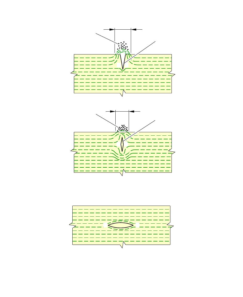
A. When a ferromagnetic component is magnetized, lines of flux are established in that component. If a
discontinuity exists in the component and that discontinuity cuts across the path of the lines of flux, the flux
is diverted and new, local poles can be set up on the surface of the component. This is known as flux leakage
(See FIGURE 51-70-00-991-001-A).
B. If fine particles of magnetic material are applied to the surface of the magnetized component, these particles
will be attracted to any flux leakages and will gather at the site of the new poles.
C. Maximum sensitivity is achieved when discontinuities lie at right angles to the direction of magnetic flux but
sensitivity is not seriously reduced with discontinuities orientated at angles up to 45˚ from the optimum
direction. Beyond 45˚ sensitivity diminishes quickly and discontinuities which lie parallel to the direction of
flux will not, cause flux leakages of sufficient strength to be detected (See FIGURE 51-70-00-991-001-A).
NOTE : Because flux leakages can be caused by discontinuities and also by changes of geometry, indications
can be relevant (cracks, laps, nonmetallic inclusions, pipe porosity, seams etc.) or non-relevant (edges,
holes, recesses, thread roots etc.) to the condition of the component. Relevant indications must be
recorded before the component is demagnetized and cleaned upon completion of the inspection.
Page 3
Feb 01/15
51-70-00-PB1
Revision n˚: 103
@A318/A319/A320/A321
NONDESTRUCTIVE TESTING MANUAL
** On A/C ALL
MAGNETIC PARTICLES
ATTRACTED TO FLUX
LEAKAGE
MAGNETIC FLUX LEAKAGE
SURFACE
DISCONTINUITY
NEAR SURFACE
DISCONTINUITY
N
S
MAGNETIC PARTICLES
ATTRACTED TO FLUX
LEAKAGE
N
S
MAGNETIC FLUX LEAKAGE
N
S
NO FLUX LEAKAGE − NO INDICATION
DISCONTINUITY PARALLEL WITH FLUX LINES
S
N
N
S
S
N
L_NT_517000_1_0010101_01_00
Page 4
Feb 01/15
FIGURE 51-70-00-991-001-A SHEET 01
Flux Leakage Relative to Discontinuity 51-70-00-PB1
Revision n˚: 103
@A318/A319/A320/A321
NONDESTRUCTIVE TESTING MANUAL
** On A/C ALL
4. Definitions
A. Longitudinal Magnetization (Magnetic Flow)
(1) The component is placed into a magnetic field so that the field couples with the component and lines of
flux flow from one pole to the other, through the component.
(2) If the magnetic flow is mainly parallel to the long axis of the component, it is said to be longitudinally
magnetized.
B. Circular Magnetization (Current Flow)
(1) An electrical current, passing through a conductor, creates a magnetic field in and around the
conductor at an angle 90˚ to the direction of current flow.
(2) When a component is magnetized, directly or indirectly in this way, it is said to be circularly
magnetized.
NOTE : Because the magnetic circuit is completed within the component there are no apparent poles
with this method (except where discontinuities or extreme changes of geometry occur).
C. Magnetic Flux Density (B)
(1) If the magnetic flux is cut at right angles to its direction of flow, the number of lines of flux, for a given
unit area, is referred to as the magnetic flux density.
D. Magnetizing Force (H)